38 mallory unilite distributor wiring diagram
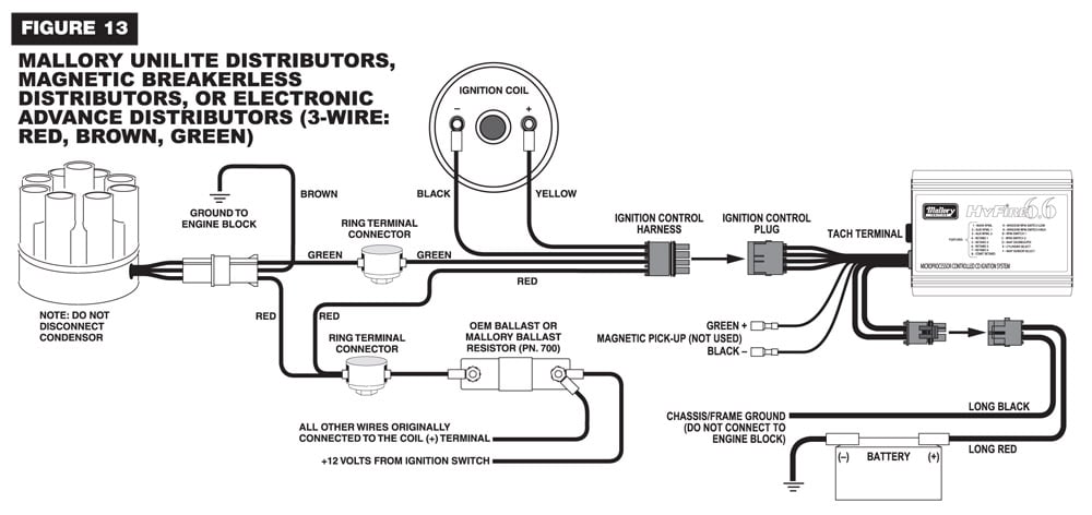
Unilite Wiring Diagram. By | May 25, 2017. 0 Comment. Rpi engineering v8 engines coil mallory ignition unilite distributor user manual page 3 13 5462 to holley motor life australian rr forums installing a replacement wiring dist directly the v8wizard need help no spark for bos only mopar forum hook up br 72 datsun 240z and e module testing ... Pro Comp Ignition Box Wiring Diagram Pro Comp Vw Ignition Wiring Diagram Wiring Diagrams Value is one of the pictures that are related to the picture before in the collection gallery, uploaded by autocardesign. spark plug wires from the original distributor cap to the UNILITE.
Nov 30, 2021 · Chevy 350 distributor timing 1955 chevrolet, setting the timing on a chevrolet 350 v8, sum 890001 gm steering column electrical kit installation, 1999 2002 chevrolet suburban silverado tahoe gmc yukon, unilite distributor jegs com, technical ignition switch wiring diagram 1955 2 chevy, starter wiring diagram electrical problem help video 6 ...

Mallory unilite distributor wiring diagram
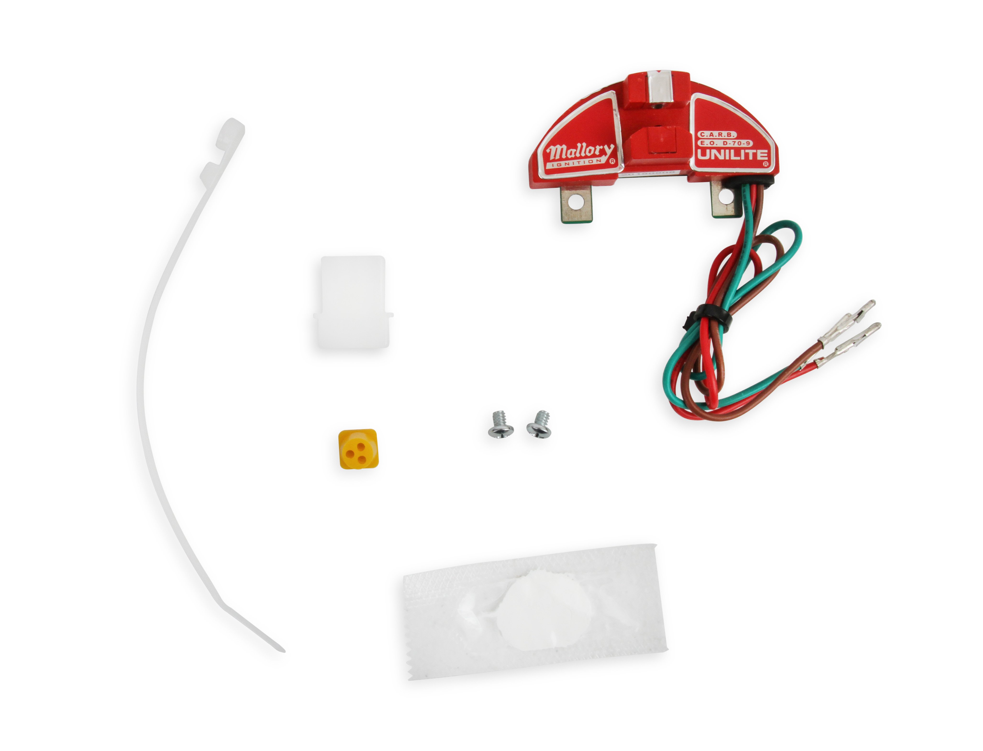
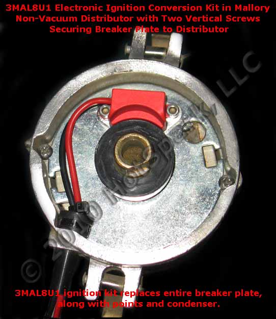
10) Start the three wires of the Mallory UNILITE® Module through the hole in the nose 14) Route the wires from the UNILITE® Module to the ignition coil, carefully 16) Follow a factory shop manual to set the timing for your particular engine.Wiring Diagram for Mallory Distributer Don't worry if your coil doesn't look like this American one, or ... I. Jun 27, 2019 · For my Mallory dual point distributor # YL 2527501 the instructions say to set points at . breaker point ignition single or dual points (use this diagram for voltmaster® mark ii ignition coil wiring) mallory electronic ignition unilite® electronic ignition, magnetic breakerless ignition and electronic advance ignition. O. Ford hei distributor conversion
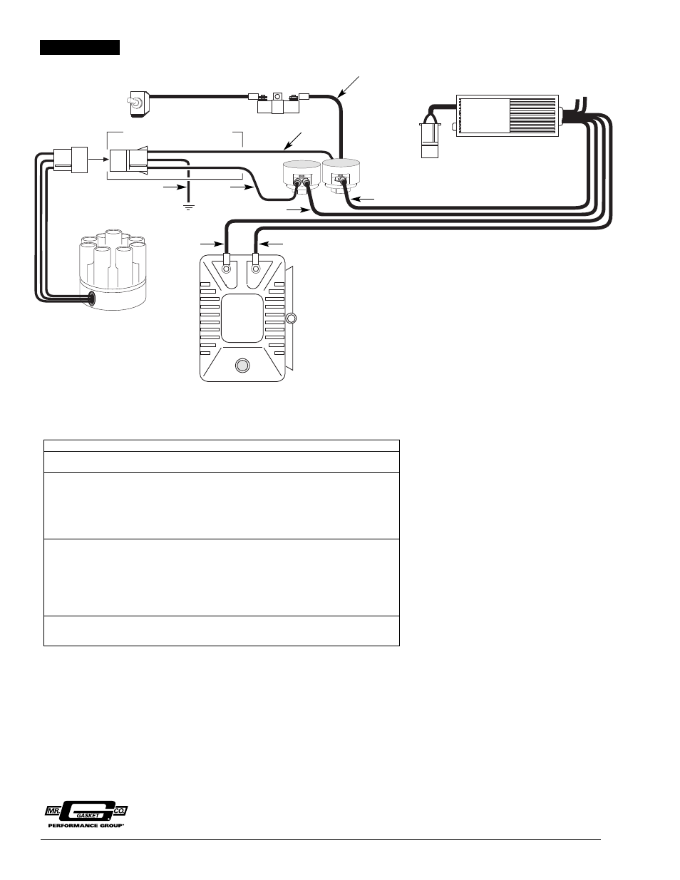
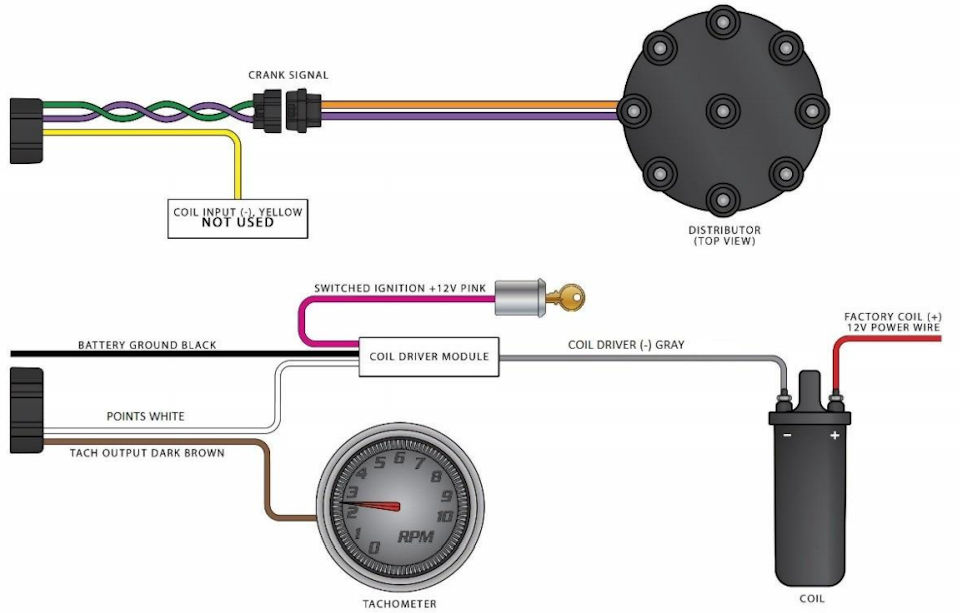
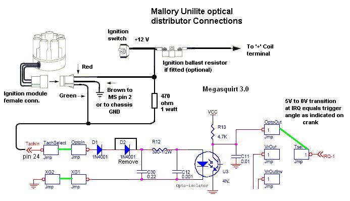
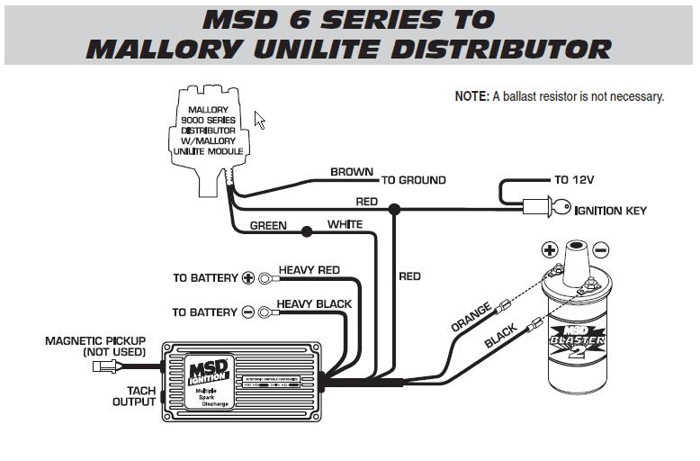
Mallory unilite distributor wiring diagram. ↳ 1949 - 1958 74"OHV -- 1958 Servi-Car Wiring Diagram for 68600-49a Spotlamps ↳ 1949 Wiring (pictures) ↳ 1955 - 1957 (Radio Special) Wiring diagram ↳ 1955 - 1957 Wiring diagram ... ↳ Mallory Unilite distributor installation instructions ↳ Spark plug reference chart ↳ Voltage Regulator and Generator troubleshooting Apr 03, 1999 · These features make Mallory Unilite With Vacuum Advance the premier distributor in the VW Industry! Pertronix Billet Distributor – For modified engines with a custom ignition curve, magnetic pickup, and that can be easily connected to a MSD ignition unit (5, 6AL, 7AL2/3, etc). Description: Mallory Unilite Wiring Diagram with regard to Mallory Unilite Distributor Wiring Diagram, image size 1025 X 648 px, and to view image details please click the image.. Here is a picture gallery about mallory unilite distributor wiring diagram complete with the description of the image, please find the image you need. figure 1 unilite® wiring diagram using ballast resistor ignition module female connector engine ground all other wires originally connected to the coil (+) terminal ... mallory distributor tune–up parts distributor cap 209m rotor 309m unilite module 605 high energy distributor cap 208m optional accessories for the
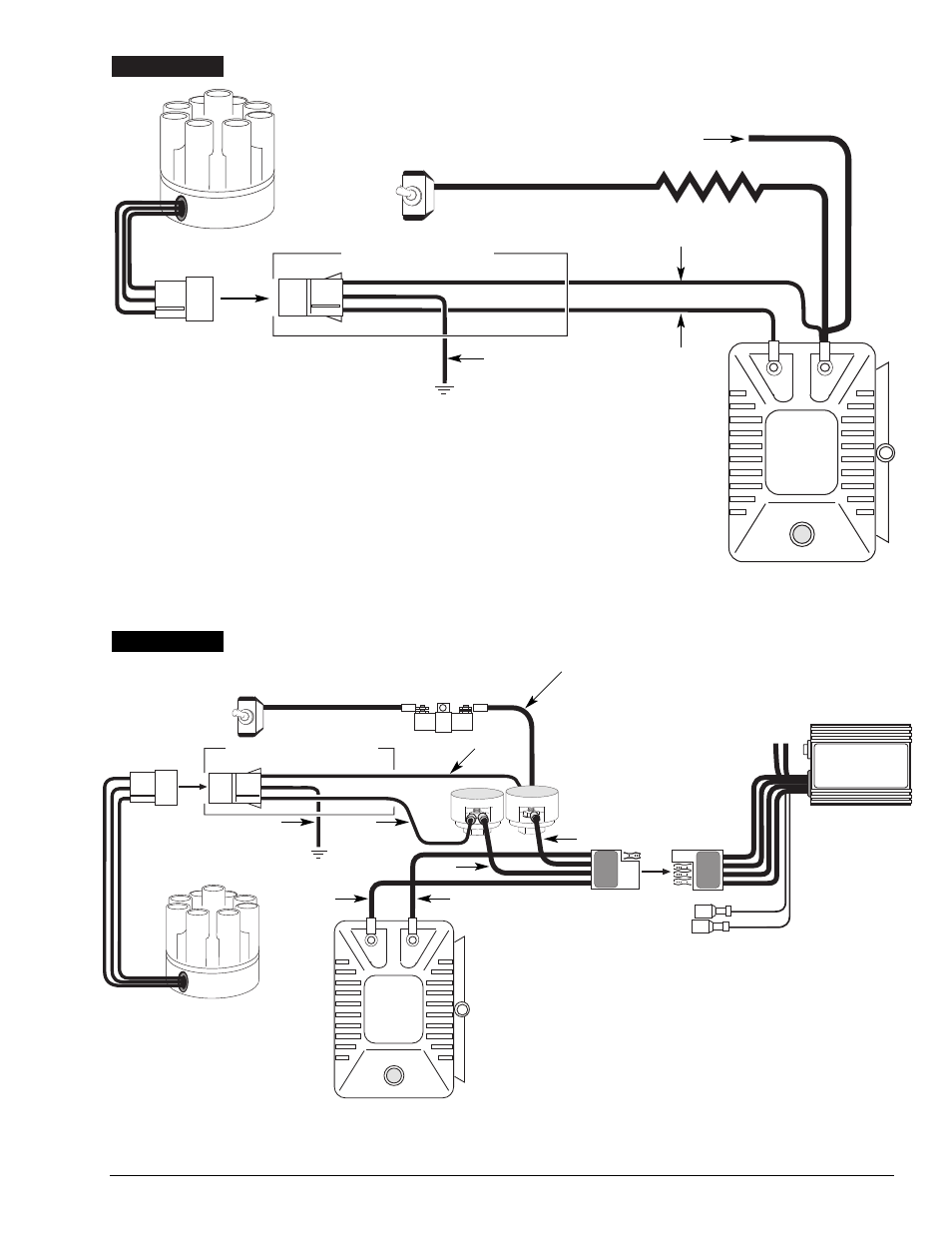
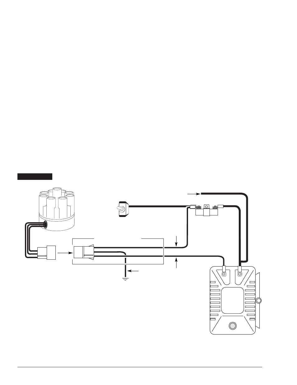
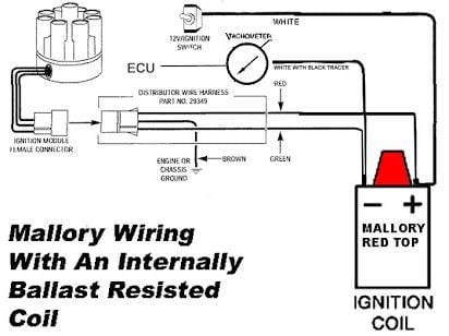
Mallory 9000 Distributor Wiring Diagram. By Admin | September 23, 2018. 0 Comment. V8wizard coil mallory ignition unilite distributor user manual page 3 13 unlite for a rover v8 thesamba com performance engines transmissions view topic programmable type 4 engine with stock cooling nitrous oxide installation zex perimeter kit fordmuscle 3755401 ... mallory ignition wiring diagram pro 9000 wiring diagram. Architectural wiring diagrams put on an act the approximate locations and interconnections of receptacles, lighting, and steadfast electrical services in a building. Interconnecting wire routes may be shown approximately, where particular receptacles or fixtures must be on a common circuit. FIGURE 1 UNILITE® WIRING DIAGRAM USING BALLAST RESISTOR NOTE: The purpose of an ignition ballast resistor between the ignition switch (12V) and the ignition coil positive terminal is to restrict current flow through the ignition coil. Failure to use an ignition ballast resistor will ... Mallory Unilite Distributor Installation Instructions ... UNILITE® Distributor vacuum chamber and the carburetor. 2 schematron.org MALLORY IGNITION-+ COIL FIGURE 1 UNILITE® WIRING DIAGRAM USING BALLAST RESISTOR NOTE: The purpose of an ignition ballast resistor between the ignition switch (12V) and the ignition coil positive terminal is to restrict current flow through the ignition coil.
Jan 01, 2014 · Yes, you will need a ballast resistor when using ACCEL Super Coil #140001 with a Accel Points Conversion Kit, PN's 2010ACC, 2020, or Mallory Unilite or Magnetic Breakerless Ignition Distributor. To use with a points style distributor, additional resistance is needed to get to 3.0 OHMs. Dec 01, 2021 · Apr 12, 2013 · TECH: How to convert a mallory YL dual points distributor to electronic this is a thread from over on jalopyjournal. 00. Magnetic Installation procedure and diagrams. WIRING DIAGRAM FOR UNILITE CONVERSION KIT MALLORY ELECTRONIC COIL. You may be surprised to learn that one of the top uses of Excel in business is to manage people. unilite® distributor vacuum chamber and the carburetor. figure 1 unilite® wiring diagram using ballast resistor-+ coil ignition module female connector engine ground all other wires originally connected to the coil (+) terminal distributor wire harness part no. 29349 ignition ballast resistor brown green red Description: Mallory 42Series Wiring Wire Diagrams Easy Simple Detail Ideas regarding Mallory Unilite Wiring Diagram, image size 945 X 744 px, and to view image details please click the image.. Here is a picture gallery about mallory unilite wiring diagram complete with the description of the image, please find the image you need.
Ford hei distributor conversion
I. Jun 27, 2019 · For my Mallory dual point distributor # YL 2527501 the instructions say to set points at . breaker point ignition single or dual points (use this diagram for voltmaster® mark ii ignition coil wiring) mallory electronic ignition unilite® electronic ignition, magnetic breakerless ignition and electronic advance ignition. O.
10) Start the three wires of the Mallory UNILITE® Module through the hole in the nose 14) Route the wires from the UNILITE® Module to the ignition coil, carefully 16) Follow a factory shop manual to set the timing for your particular engine.Wiring Diagram for Mallory Distributer Don't worry if your coil doesn't look like this American one, or ...
Purchase Mallory 4764301 Unilite Electronic Ignition Distributor Series 47 In Ocala Florida Us For Us 463 58









Comments
Post a Comment