39 ballast resistor wiring diagram
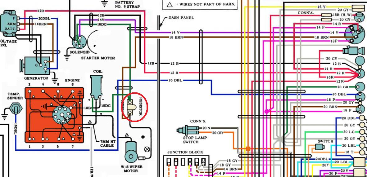
Don't bypass the ballast resistor, if you do that you'll overstress the coil. If you look in those diagrams you'll see that +12V is on B and Coil+ is on F. Between B & F is a resistance of about 2 Ohms, whilst cranking the starter 12V is applied to C and this has about 1 Ohm between C & F. Jun 8, 2019 - Looking for information about Ignition Coil Distributor Wiring Diagram? you are right here. You may be a professional who wishes to search for referrals or fix existing problems. Or you are a trainee, or maybe even you who just wish to know about Ignition Coil Distributor Wiring ...
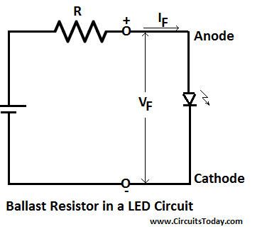
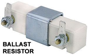
Oct 17, 2017 — A ballast resistor is used in a circuit to limit the current and hence prevent it from over current faults. Here, as the current in the circuit ...

Ballast resistor wiring diagram
The wiring diagram shown below was obtained from Pertronix to show the proper hookup for a Pertronix Igniter in a car wired for positive ground, or earth if you prefer. It goes without saying that this is valid only for cars without ballast resistors, viz., our T-series cars. ignition coil ballast resistor wiring diagram helloo ignition coil coil diagram. Image Source : www.pinterest.com. 2048 x 1536 · jpeg. bypassing ballast resistor installing pertronix ignition bodies mopar forum. Image Source : www.forabodiesonly.com. 1068 x 610 · jpeg. voltage resistance coil ballast resistor electrical classic zcar club Figure 1 unilite wiring diagram using ballast resistor coil ignition module female connector engine ground all other wires originally. The purpose of an ignition ballast resistor between the ignition switch 12V and the ignition. Gasket performance group memphis ave. Locate the ignition ballast resistor or loom resistance wire.
Ballast resistor wiring diagram. August 26, 2016 - You will most likely not get any warning of its failure; it may be working fine today and give out tomorrow. A quick and easy way to diagnose ballast resistor failure is to bypass it by running a temporary jumper wire from the battery to the coil. If it starts and remains running, you’ve ... Make sure that your vehicle is equipped with an ignition ballast resistor (or loom resistance wire) in the wire between the ignition switch and the coil (+) terminal. If you find your vehicle is not equipped with an ignition ballast resistor,install an ACCEL Ignition Ballast Resistor Part No.150001 in series in the wire from the ignition switch. Ignition ballast resistor wiring diagram No brainer wiring question ballast resistor bmw 2002 and other '02 bmw 2002 faq Installation e spark Accuspark wiring diagrams Ford ignition resistor wire diagram wiring diagrams bait mute Old 12 volt ignition coil wiring diagram for ford wiring diagram ... 05/09/2020 · Ford Ballast Resistor Wiring Diagram. Print the wiring diagram off plus use highlighters to trace the signal. When you make use of your finger or perhaps the actual circuit with your eyes, it is easy to mistrace the circuit. 1 trick that We 2 to printing a similar wiring plan off twice. Upon one, I’ll trace the current movement, how it ...
April 8, 2017 - 1973 - 1979 F-100 & Larger F-Series Trucks - Ballast resistor or resistor wire? - I'm driving a 1974 ford f250 360 pre-electronic ignition, just replaced the ignition with the newest generation pertronix module and coil- what a huge difference in performance and mileage. Description: Ignition Coil Ballast Resistor Wiring Diagram with Ignition Coil Ballast Resistor Wiring Diagram, image size 609 X 360 px, and to view image details please click the image. Here is a picture gallery about ignition coil ballast resistor wiring diagram complete with the description of the image, please find the image you need. 15/12/2020 · Ignition Coil Ballast Resistor Wiring Diagram from i.pinimg.com. Print the cabling diagram off plus use highlighters to be able to trace the circuit. When you use your finger or even follow the circuit together with your eyes, it is easy to mistrace the circuit. 1 trick that We use is to print the same wiring picture off twice. FIGURE 1 UNILITE® WIRING DIAGRAM USING BALLAST RESISTOR NOTE: The purpose of an ignition ballast resistor between the ignition switch (12V) and the ignition coil positive terminal is to restrict current flow through the ignition coil. Failure to use an ignition ballast resistor will eventually destroy the Ignition Module.
Chevy Ballast Resistor Wiring Diagram dadrl how to disable drls lightsout org, technical help university motors online, ignition coil distributor wiring diagram wiring forums, fbo ignition systems mopar micro processor ignition, engine willystech, automotive car truck light bulb connectors sockets wiring, full text of new internet archive, electrical willystech, mallory unilite … Ballast Resistor: If your vehicle has a ballast resistor in line with the coil wiring, it is recommended to bypass it. ROUTING WIRES: The spark plug wires should be routed away from direct heat sources, such as exhaust manifolds and headers and any sharp edges. The trigger wires should be routed separate from the other wires and spark plug wires. This Video explains how the Ballast Resistor Works.For additional How-to Tutorials Visit our Website: http://www.howstuffinmycarworks.com Unsure how to tell if your Classic British Car has a ballast resistor or not? The Moss Motors Tech department has put together this video tip to show you how...
Dave's Place - Chrysler Electronic Ignition System Test
Some customers report that bypassing the ballast resistor by disconnecting the ballast feed wire ( from the starter solenoid or built into the loom) and providing a direct 12 volt feed from the starter solenoid/relay or fuse box to the ignition coil has proved to be a success and has given good results.
After ignition module replacement, new issue | Rolls-Royce ...
The original car used a standard ignition circuit that incorporated a single or dual-point distributor. Most kits today will use an electronic distributor, and many use a multi-spark unit such as the MSD · When you hook up your system, check whether the distributor requires a ballast resistor.
62 ballast resistor purpose and readings? - CorvetteForum ...
However, the ballast-resistor component equipped models still used the white ignition feed wire to the coil that actually ran the 6-volt coil system. The only truly definite way of discovering which your car has is by testing the voltage at the coil lead feed with the ignition on. 12-volt says it's the old system, 9-volt identifies it as ...
how to wire a ballast resistor Questions & Answers (with ...
August 31, 2011 - Due to the EU's Global Data Protection Regulation, our website is currently unavailable to visitors from most European countries. We apologize for this inconvenience and encourage you to visit www.motortrend.com for the latest on new cars, car reviews & news, concept cars and auto show coverage, ...
Ballast Resistor - Working, Uses, Applications and Types
Some brands utilized a resistor in the coil or a resistor wire hidden in the wiring from the ignition switch, but Mopar put their resistor (or ballast resistor) on the firewall or inner fender, causing some to misidentify it as a part of the charging system. In simple terms, the ballast resistor ...

✓ What Does A Ignition Ballast Resistor Do
The Ballast Resistor is a high failure item. Most people carry a spare Ballst Resistor with them. Corroded wiring connectors and solder joints will reduce voltage to the ignition circuitry resulting in hard starting and phantom problems.
Ballast Resistor - Working, Uses, Applications and Types
Step 3. Cut a piece of wire long enough to reach from the other terminal of the ballast resistor to the "Bat", "+" or "B+" terminal of the coil. Strip 1/2 inch of insulation from each end of this wire and crimp a connector onto each end. Connect the wire to the unused terminal of the ballast resistor and to the previously identified terminal of ...
Ballast Resistors Explained + Ballast Testing Procedure ...
Nov 04, 2018 · badland wireless winch remote control wiring diagram; ballast bypass led t8 wiring diagram; ballast resistor wiring diagram; baofeng speaker mic wiring diagram; barrina led t5 wiring diagram; basic chevy hot rod wiring diagram; basic hot rod wiring diagram; basic led strip light wiring diagram; basic reverse light wiring diagram; basic shed ...

Big Block Wiring
The ballast resistor get's installed on the wire from the ignition switch to the positive side of the ignition coil and it's the wire that is hot when the key is on run not start. the start coil wire should still have 12 volts. One second and I'll pull up the wiring diagram. Ford Ignition Wiring Diagram - wiring diagram plymouth reliant ...
How to wire mid-1970s through mid-1980s ignition systems ...
2020-12-15 · Ignition Coil Ballast Resistor Wiring Diagram from i.pinimg.com. Print the cabling diagram off plus use highlighters to be able to trace the ...
Technical - Unilite wiring question ...... yes, another one ...
Apr 4, 2017 — I'm trying to wire the bypass wire on the schematics. That goes from starter solenoid "R" to coil "+" bypassing the ballast resistor.
ELECTRICITY AND WIRING
WIRING PROCEDURE The 3 wires coming from the UNILITE® Distributor must be connected using the distributor wire harness provided. (see Figures 1 and 2). RED WIRE: If you use loom resistance wire, connect to the coil (+) terminal. If you use a ballast resistor, connect to 12 volt side of ballast resistor. GREEN WIRE: Connect to the coil ...

Ignition Coil Distributor Wiring Diagram - Wiring Forums ...
RESISTOR COLOR CODE GUIDE 2 0 x10,000 10 % 20 x 10,000 = 200,000 1,000 = 1K Resistor = 200 K with a 10 % Tolerance+-First Band Second Band Multiplier Band Tolerance Band Equation The Gold or Silver band is always placed to the right. The resistor value is read from the left to right. If there is no tolerance band, then find the side that has

How the Ballast Resistor Works
As a matter of fact, a bad diode trio in a conventional alternator can do the same damage. 2 wiringall.com MALLORY IGNITION-+ COIL FIGURE 1 UNILITE® WIRING DIAGRAM USING BALLAST RESISTOR NOTE: The purpose of an ignition ballast resistor between the ignition switch (12V) and the ignition coil positive terminal is to restrict current flow ...
Ballast Resistor | The De Tomaso Forums
9. Route the blue wire to the ballast resistor. Avoid the exhaust manifolds and sharp edges, follow existing wiring harnesses if possible. 10. Disconnect the wires from both ends of the original ballast resistor. Remove the old ballast resistor and install the new ballast resistor in its place. Do not reconnect the wires. 11.
240 Won't Start - Weak Orange Spark From Coil. | Volvo Owners ...
Ignition coil ballast resistor wiring diagram No brainer wiring question ballast resistor bmw 2002 and other '02 bmw 2002 faq Compatible ignition coils, ballast resistors, hot spark electronic ignition Accuspark wiring diagrams Installation e spark Wiring diagram ignition coil resistor ...

DISTANCE PIECE | Martin Robey
run through a ballast resistor or wire. Bypass any resistance unit to provide full 12V key ON power to the coil and module. If you set up a battery on a bench and hook up all the wires as shown you can check the spark by toggling the point lead (#5) to ground. You will see a nice hot spark out of the secondary. The circuit is quite simple and works

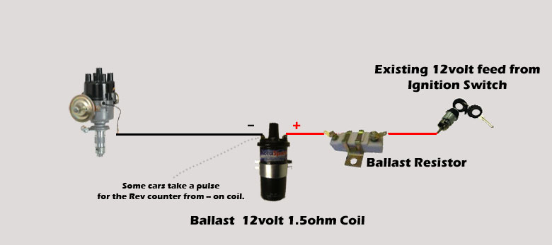
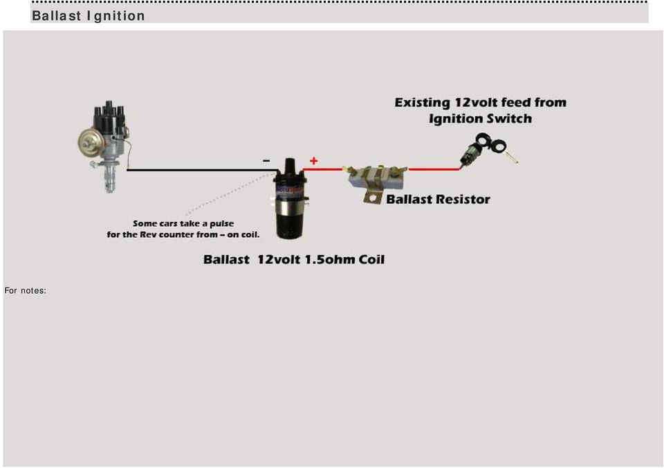
12V Ballast Ignition Solenoid
My wiring diagram has a line with a squiggle. My ballast resistor has 2 connectors and another i presume to be earth. I have a white wire from the ignition switch which when attached to the coils gives me a spark but i can't get a spark through the resistor.
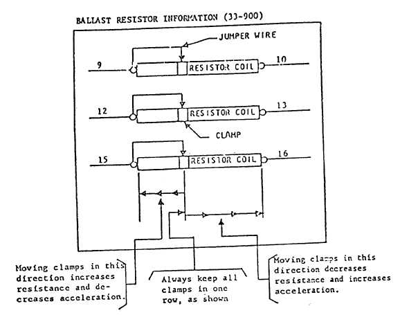
SAMPLE BALLAST RESISTOR DIAGRAM
Then when I hook the wire from the resistor to the coil my voltage drops back to like 9.6 going in to the resistor and 4.6 coming out and the resistor gets quite hot. The ballast resistor itself has 1 ohm resistance across the terminals with nothing connected. Also the ballast resistor gets so hot that it actually smokes but the wiring seems ...
240z electronic ignition help - Page 2 - Ignition and ...
Ignition coil resistor wiring diagram ... wiring diagram full version hd quality wiring diagram soadiagram assimss it Dodge ballast resistor wiring wiring diagram other issue 1969 ford resistor wire diagram wiring diagrams bait brown Gm coil wiring diagram data wiring diagrams supply ...

Greg Marsh Enterprises - Custom Wiring Diagram
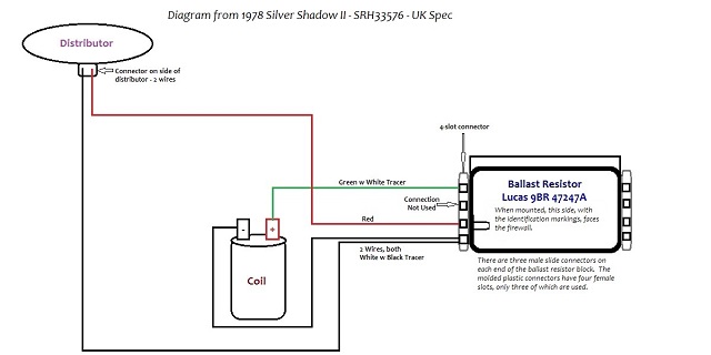
Hi - can anyone explain, or does anyone have a simplified diagram showing how the wiring should run between the ignition coil, ballast resistor and the distributor. Someone previously has taken the ballast resistor out of circuit, and removed all the wiring, so not sure how it should be wired back in. This is for a Silver Shadow II.

No brainer wiring question - Ballast resistor - Page 2 - BMW ...
leak may be in your ballast resistor connections or your ignition (key) switch. This page links directly to all of my 6 volt and 12 volt wiring diagrams. specific diagrams for the Ford-Ferguson 9N, 2N, Ford 8N, 53 Jubilee, and Ford ,, tractors. Links to other sites often break when they rename or move files. w/ Wrap Around Back Rest.
Australian RR Forums: Ballast Resistors Through the Years
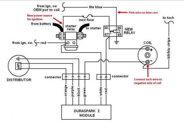
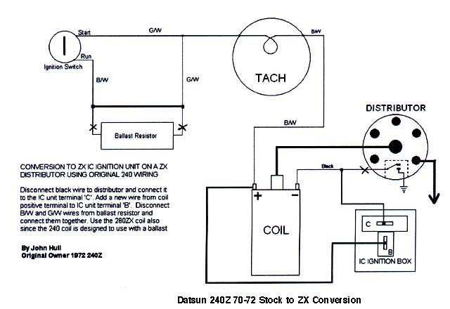
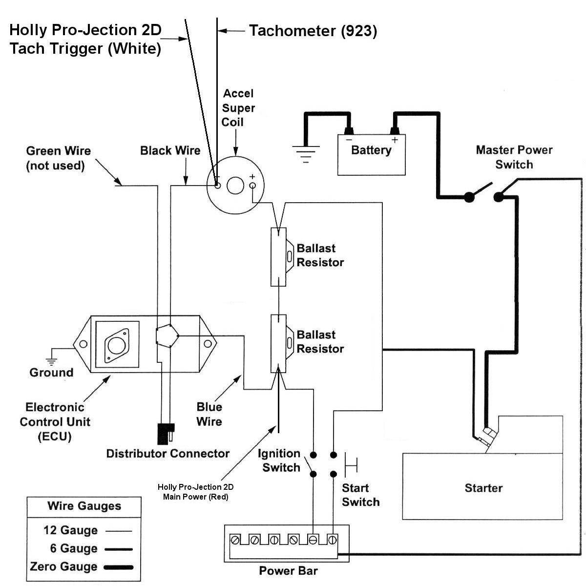
The following diagram shows the 5 pin box with dual ballast resistor; "Start" is only hot (+12V DC) during cranking, and "run" is hot (+12V DC) from the moment you turn the key on, through crank, and after crank.
AccuSpark
0-10V dimming wiring diagram 0-10V dimmer switch Leviton IP710-LFZ or equal For other types of dimming control systems, consult controls manufacturer for wiring instructions switched hot (black) switched hot (red typical) low voltage dimming wires (purple & gray typical) + Electrical Panel hot (black typical) 120V or 277V, 60 Hz
AccuSpark Fitting guide FITTING INSTRUCTIONS, AND WIRING ...
21/11/2018 · Ignition troubleshooting accuspark wiring diagrams ballast resistor duel spark coil diagram igniter and with australian rr forums resistors how to replace a chrysler electronic system test ing guide Ignition Troubleshooting Accuspark Wiring Diagrams No Brainer Wiring Question Ballast Resistor Bmw 2002 And Other 02 Faq Diagram Duel Spark Ignition Coil …

Norton Commando Wiring Diagram + Tri-Spark
03/04/2021 · Ballast Wiring Diagram – ballast resistor wiring diagram points, ballast wiring diagram, ballast wiring diagram t12, Every electric arrangement is made up of various distinct pieces. Each component ought to be set and linked to different parts in specific way. Otherwise, the structure will not function as it should be.
How to Test an Ignition Coil
Ignition ballast resistor wiring diagram No brainer wiring question ballast resistor bmw 2002 and other '02 bmw 2002 faq Accuspark wiring diagrams Compatible ignition coils, ballast resistors, hot spark electronic ignition Wiring diagram ignition coil resistor hobbiesxstyle Ignition troubleshooting ...

No brainer wiring question - Ballast resistor - BMW 2002 and ...
Step 4: Install Ballast Resistor. Set the ballast resistor up to the firewall and screw the clamps in place. Step 5: Connect Wires to Positive. Strip the end of the positive wire from the ignition, and connect it to the positive end of the resistor. From the other terminal on the resistor a wire goes to the positive on the coil.

How To Install An Electronic Distributor - Car Electrical ...
Aug 11, 2017 · badland wireless winch remote control wiring diagram; ballast bypass led t8 wiring diagram; ballast resistor wiring diagram; baofeng speaker mic wiring diagram; barrina led t5 wiring diagram; basic chevy hot rod wiring diagram; basic hot rod wiring diagram; basic led strip light wiring diagram; basic reverse light wiring diagram; basic shed ...

anything I can substitute for a ballast resistor? - Ford ...
to the distributor, as in a GM HEI distributor, to a ballast resistor as in a points type distributor, or to the ignition power source for an aftermarket ignition module such as an MSD module. See the installation instructions for the type of distributor you are using for specific connection requirements. 6. Select the white Wiper feed wire (93).
Ballast Resistor Not Resisting? - Electrical - The Classic ...
5 2.0 ABOUT THESE INSTRUCTIONS The contents of these instructions are divided into major Sections, as follows: 1.0 Introduction 2.0 About These Instructions 3.0 Tools Needed

240z Coil and Ballast Resistor Installation Help - ZDriver.com
Starting System & Wiring DiagramAmazon Printed Bookshttps://www.createspace.com/3623931Amazon Kindle Editionhttp://www.amazon.com/Automotive-Electronic-Diagn...
Ignition issue 71 302 only runs in crank position | Ford ...
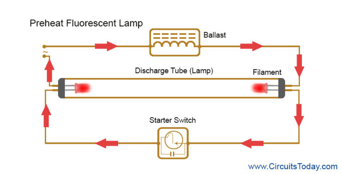
Instant start ballasts can only be wired in parallel according to the diagram on the ballast. Changing the wiring on a fluorescent light fixture from rapid start to instant start, involves changing the wiring from series to parallel. 1 Lamp Rapid Start Ballast Diagram.
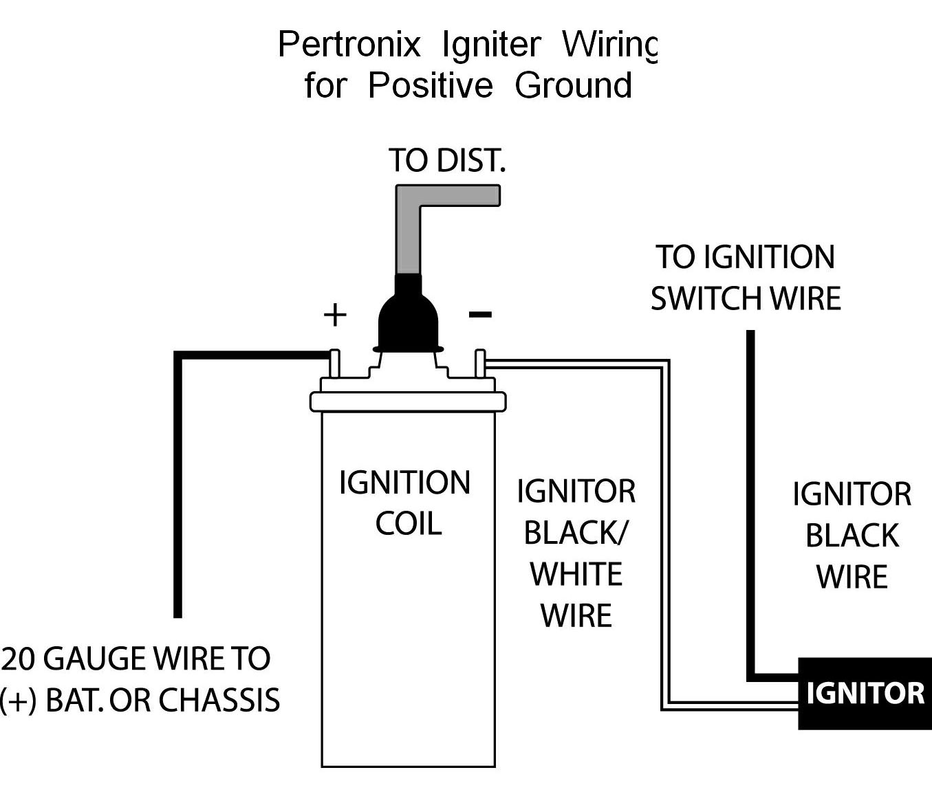
Pertronix Positive Ground Wiring
November 16, 2008 - Hey dood, Diagram attached for wiring of points dizzy and coil with ballast resistor. The Coil - does not go direct to earth. (If you have connected it this way and also connected the Coil+ to Battery, the coil will be constantly drawing current and will overheat and also flatten the battery) ...
Ballast Resistor Question - Page 1 - Sweptline.ORG
This wiring diagram is for the 1980 and later four pin ignition module. If you have an ignition harness with five wires, just don't connect the dark green wire that would go to pin 3. I Installed a Jacobs computer ignition, and it doesn't require a ballast resistor.
1960 Wiring (starter, electonic ignition and Ballast Resistor ...
Ballast resistor wiring diagram points. Resistors wiring diagrams duration. According to the wiring diagram i have it goes to the ignition switch. In simple terms the ballast resistor in a mopar limits the amperage or current flow through the coil while the engine is running thereby extending the life of the coil and breaker points of.

Before there was BHKZ: SWB engine electrics - Pelican Parts ...
All 1200s used a ballast resistor until the 1990 models. [edit]. Early 1200. NOTE: The 1973 Wiring Diagram doesn't show a resistor, but it definitely has one.

Bypassing ballast resistor | For A Bodies Only Mopar Forum
09/11/2018 · Pertronix wiring diagram in addition chevy ballast resistor wiring diagram together with 6 0 engine cooling diagram html furthermore mustang voltage regulator wiring diagram also 92 f engine diagram moreover toyota auris fuse box location moreover club car ignition wiring diagram in addition ford msd ignition wiring diagram together. Find great deals …
Help with ballast resistor wire replacement on '67 GTO ...
Update: sadly I think the diagrams are incorrect. They do not show the correct circuit for the fuel pump power. the power for the fuel pump (not the fuel pump relay) goes through the ballast resistor. The resistor is not shown in the wiring diagram and neither is the electronics that bypass the resistor.
Comments
Post a Comment