41 septic tank float switch wiring diagram
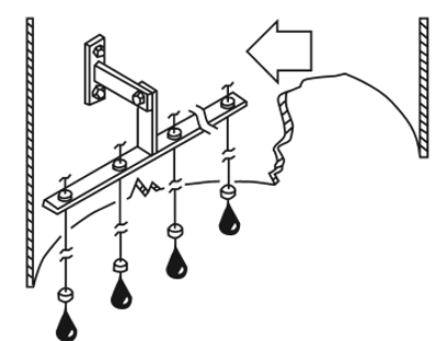
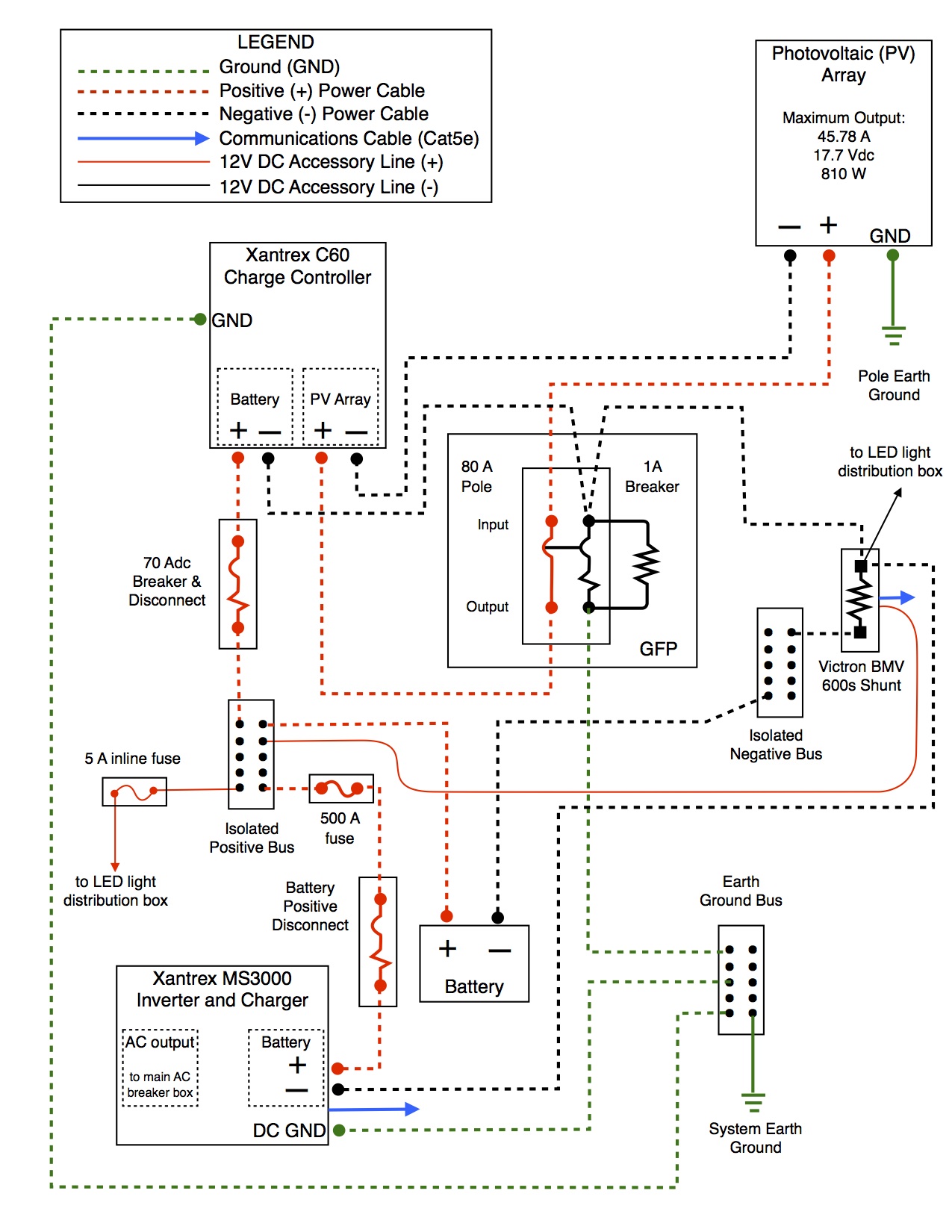
PDF Instructions Float Switch Settings and Adustments • The float switches shouldn't interfere with one another during this check. Step 3d: If the float switches interfere with another, adjust the collar horizontally until the float switch is clear of the float switch(es) above or below it. Step 3e: When the float switch(es) are adjusted and have vertical and horizontal 3 Wire Float Switch Wiring Diagram - easywiring Let s start with the most basic float switch. Wiring diagram of 2 float switch for two tanks wiring diagram of 3 motors diagram guitar fender also well and septic systems diagnostics. Switched outlet wiring diagram. 2 built in bilge running indicator. Each part ought to be set and connected with different parts in particular manner.
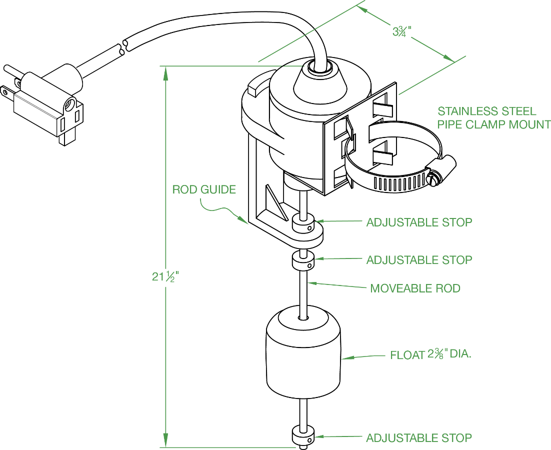
Septic Tank Float Switch: Functions, Types & Problems For a pump to turn on, the water level must have reached a level that triggered the sensor. Septic tank float switches also alert you to when the water level gets too high or when other problems arise. This important function takes the stress off your shoulders. You don't have to monitor when a pump needs to be put on or off.

Septic tank float switch wiring diagram
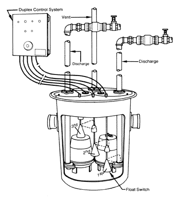
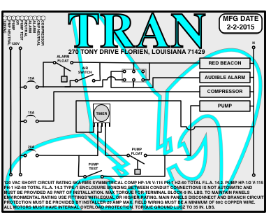
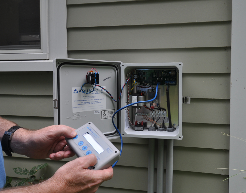
Septic Tank Alarm Wiring Diagram - Wiring Diagram and ... Septic Tank Alarm Wiring Diagram. Pump alarm septic tank alarms contractor talk aerobic system faqs q a on duplex sewage pumps control panels tran t2 panel controlonitor systems aquaworx box 50b007 bio d sump high water float submersible. Brandywine Septic Services Inc Pump Alarm 610 869 0443. Septic Pump Alarm Wiring Diagram - IOT Wiring Diagram Aquaworx Septic Pump Control Box Infiltrator. Float Switch Installation Wiring Control Diagrams Apg. Spi Bio B Double Light Control Panel For Aerobic Septic Systems 50b006 Tg Wastewater. Sump Pump High Water Alarms Float Switch Septic Tank Control Panels Floats. Spi Bio Pump Control Panel With High Water Alarm Model 50b010 Whap Tg Wastewater. Septic pump float switch | Electrician Talk 127 Posts. #17 · Jan 27, 2012. If it has two floats, it has a relay in it. white is neutral black is hot and red is switch wire. when the tank fills with water both floats tip up, the short float switches the power to the red wire which starts the pump. when the water level drops the pump turns off when the the long float tips down.
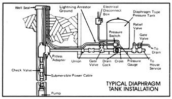
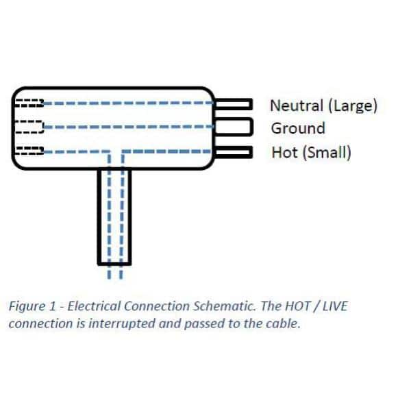
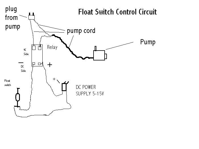
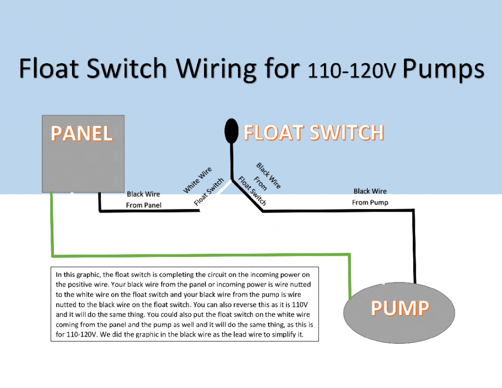
Septic tank float switch wiring diagram. Septic Tank Electrical Wiring Diagram - Diagram Sketch 12 Awesome Wiring Diagram For 220 Volt Submersible Pump Ideas Bacamajalah Electrical Diagram Submersible Pump Ceiling Fan With Remote. Septic Pump Float Switch Wiring Diagram Tank Fresh Amazing Gallery The Best Electrical Circuit Electrical Circuit Diagram Electrical Wiring Diagram Boat Wiring. New Hyster S50xm Wiring Diagram And Forklift ... Electric Wiring Diagram Septic - Worksheet And Wiring ... Septic Tank Float Switch Wiring Diagram - septic tank 3 float switch wiring diagram, septic tank float switch wiring diagram, Every electrical arrangement is made up of various different pieces. Each component ought to be placed and connected with other parts in specific manner. If not, the structure won't work as it ought to be. How To Hard Wire A Float Switch To A Submersible Pump The float switch has two legs. One leg of the float switch will connect to the hot wire from the panel; the other leg will connect to the hot wire from the pump. (Please note: Most float switches have a white and black wire, which means you will most likely have a white to black connection. This is perfectly normal and the correct way to do it.) How To Wire a Septic Tank Pump & Alarm System - YouTube Enclosure Box I Used: Alarm with Float: Septic Pump: with Light and...
Septic Tank Alarm, Float Switch, High Water Alarm, Septic ... Septic Solutions® carries a large selection of septic tank alarms, control panels, and float switches. Our septic tank alarm product line covers many applications including various high water alarms, control panels for aerobic treatment systems, simplex pump station control panels, duplex pump station controls, float control switches, float pump switches, and miscellaneous parts. How to Troubleshoot Septic Float Switches - Hunker Step 4. Check the circuit breaker or the GFCI plug (Ground Fault Circuit Interrupter) for the float switch to make sure it hasn't tripped. The GFCI plug will trip if moisture gets into the outlet. A light will come on that indicates the circuit has tripped. Try pushing the button on the GFCI plug to reset it, or flip the switch for the circuit ... Septic Tank Float Switch Wiring Diagram Gallery - Wiring ... Please download these septic tank float switch wiring diagram by using the download button, or right select selected image, then use Save Image menu. Wiring diagrams help technicians to determine the way the controls are wired to the system. Many people can understand and understand schematics called label or line diagrams. PDF Installation Manual - The Septic Store Float Arrangement & Splice Box Wiring Diagram EDW-FS-S-1 4. VCOM-S RO Operation EIN-CP-OP-498. ... septic tank and located at a convenient height (about five feet above grade). 2. The panel should be securely fastened to a 4 x 4 post that has been ... = Audio Silence Switch = Con rls icuBeak = Fuse, 120VAC/1A = Motor Contactor
Float Switch Wiring Diagram For Water Pump - Studying Diagrams Wiring diagram of 2 float switch for two tanks wiring diagram of 3 motors diagram guitar fender also well and septic systems diagnostics. They certainly dont apply in all scenarios especially when additional control equipment is needed to handle large motors. Electrical ac dc 3 wire 240v for well pump i have a 220v water well pump submersible ... Float Switch Wiring Diagram – Wiring Sample Aerobic Septic System Wiring Diagram Download. Float Switch is basically is the combination of NO and NC circuit that changes its contacts depends upon the alignment at which it is placed. One leg of the float switch will connect to the hot wire from the panel. However some of the models have isolated switch points that you can wire to a. Septic Tank Float Switch Wiring Diagram - Cadician's Blog Septic Tank Float Switch Wiring Diagram Fresh Champion Pump Wiring - Septic Tank Float Switch Wiring Diagram Wiring Diagram arrives with several easy to stick to Wiring Diagram Guidelines. It really is supposed to aid each of the typical person in developing a proper system. These instructions will probably be easy to comprehend and use. Septic Tank Electrical Wiring Diagram - Studying Diagrams Septic tank float switch wiring diagram Septic Tank Electrical Wiring Luxury About Electrical House Wiring Lovely Electrical Wiring Diagram for A. Injunction of 2 wires is usually indicated by black dot to the junction of two lines. The diagram below references a V pump and wiring.
44 septic tank electrical wiring diagram - Wiring Diagram ... But, it does tend to become more complex. Figure 5 below shows a schematic diagram... Septic Tank - Components and Design of Septic Tank Based on... Septic tank can be defined as primary sedimentation tank for disposal of night soil. Top of the ventilation pipe is provided with a mosquito proof wire mess or cowl. Septic tank electrical wiring ...
Septic Tank Float Switch Wiring Diagram - schematron.org Jan 14, 2019 · Below is a diagram of what is described in the paragraph above.Septic Solutions® carries a large selection of septic tank alarms, control panels, and float switches. Our septic tank alarm product line covers many applications including various high water alarms, control panels for aerobic treatment systems, simplex pump station control panels ...
Septic Tank Float Switch Wiring Diagram - Wiring Diagram Dec 11, 2021 · Septic Tank Float Switch Installation 51 With Level Wiring Diagram – Septic Tank Float Switch Wiring Diagram. Wiring Diagram contains many in depth illustrations that display the link of various products. It contains instructions and diagrams for various kinds of wiring techniques as well as other products like lights, windows, etc.
Float Switch Wiring Diagram - easywiring Septic tank float switch wiring diagram shahsramblings septic tank float switch wiring diagram the diagram provides visual representation of a electric structure. Float switch wiring diagram. Older float switches work by opening and closing circuits dry contacts as water levels rise and fall. Float switches of the 21st century have come much ...
Float Switch Installation Wiring & Control Diagrams - APG ... Let's start with the most basic float switch: a two-wire, single-pole, single-throw float switch.The rising action of the float can either close (i.e., turn on) a "Normally Open" circuit, or it can open (turn off) a "Normally Closed" circuit.Installation scenarios might include a Normally Open float switch turning on a pump to empty a tank (Control Schematic 2), or a Normally Closed ...
Septic Tank Float Switch Wiring Diagram - Free Wiring Diagram Size: 164.83 KB. Dimension: 1342 x 820. DOWNLOAD. Wiring Diagram Pics Detail: Name: septic tank float switch wiring diagram - Wiring Diagram for Float Switch Inspirationa Septic Tank Float Switch Wiring Diagram New Dual Tank Septic. File Type: JPG. Source: eugrab.com. Size: 1,023.44 KB. Dimension: 3905 x 2507.
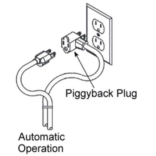
Duel float septic pump - Electrician Talk John Brylinski. I wired a duel float septic pump yesterday. The upper and lower float were factory wired to an "encapsulated" junction box within the tank, connecting to a 3 wire (no ground) with a male cap which exited the tank, into which the 220 volt cord end from the pump "piggy-backed". By this I mean the pump plugged into the side of the ...
Septic Pump Float Switch Wiring Diagram Gallery - Wiring ... Sep 07, 2019 · Name: septic pump float switch wiring diagram – Septic Tank Float Switch Wiring Diagram Best How to Replace A Broken Air Conditioner Condensate; File Type: JPG; Source: kmestc.com; Size: 289.05 KB; Dimension: 1539 x 954; Essential Tips for Safe Electrical Repairs. Repairing electrical wiring, a lot more than another household project is ...
Septic Tank Float Switch Wiring Diagram - Wirings Diagram Jan 15, 2022 · According to earlier, the traces in a Septic Tank Float Switch Wiring Diagram signifies wires. At times, the cables will cross. But, it doesn’t imply link between the wires. Injunction of 2 wires is usually indicated by black dot to the junction of two lines. There’ll be principal lines that are represented by L1, L2, L3, and so on.
Septic pump float switch | Electrician Talk 127 Posts. #17 · Jan 27, 2012. If it has two floats, it has a relay in it. white is neutral black is hot and red is switch wire. when the tank fills with water both floats tip up, the short float switches the power to the red wire which starts the pump. when the water level drops the pump turns off when the the long float tips down.
Septic Pump Alarm Wiring Diagram - IOT Wiring Diagram Aquaworx Septic Pump Control Box Infiltrator. Float Switch Installation Wiring Control Diagrams Apg. Spi Bio B Double Light Control Panel For Aerobic Septic Systems 50b006 Tg Wastewater. Sump Pump High Water Alarms Float Switch Septic Tank Control Panels Floats. Spi Bio Pump Control Panel With High Water Alarm Model 50b010 Whap Tg Wastewater.
Septic Tank Alarm Wiring Diagram - Wiring Diagram and ... Septic Tank Alarm Wiring Diagram. Pump alarm septic tank alarms contractor talk aerobic system faqs q a on duplex sewage pumps control panels tran t2 panel controlonitor systems aquaworx box 50b007 bio d sump high water float submersible. Brandywine Septic Services Inc Pump Alarm 610 869 0443.













Comments
Post a Comment