43 stirling engine pv diagram
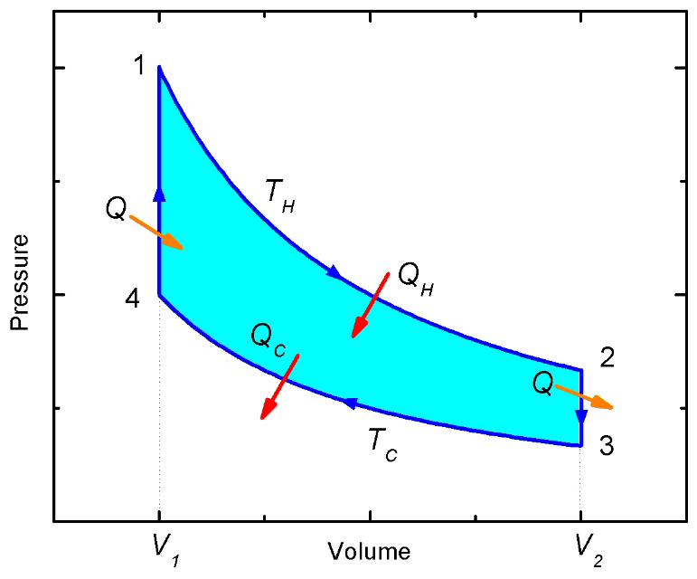
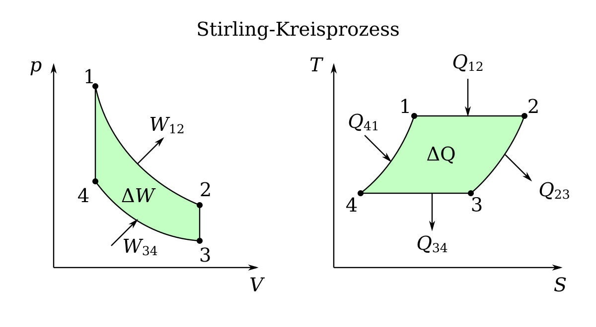
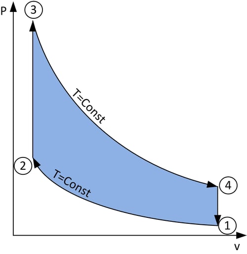
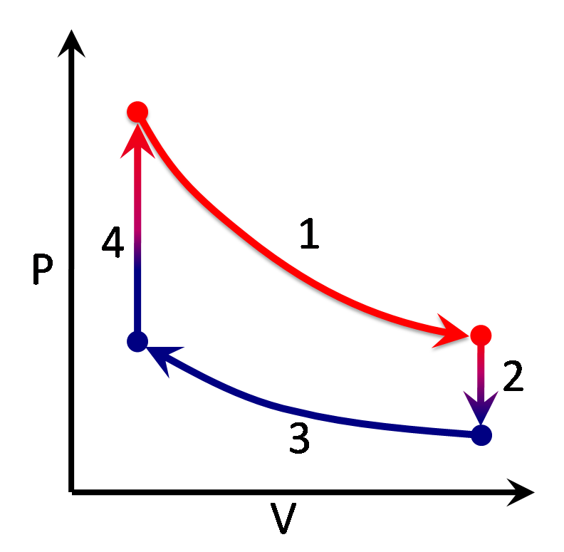
PDF Power Generation From Low Temperature | 1.3 The Stirling engine Figure 5: The isothermal Stirling engine model showing (a) the temperature profile through the compression and expansion spaces in the engine, and (b) the resulting indicator diagram where the area inside the diagram represents the indicated power of the cycle. PDF Stirling Engine Assessment 2. TECHNOLOGY OVERVIEW. Mechanical Configurations of Stirling Engines. Examples of Kinematic Stirling Designs. Work per cycle equals area inside loop. Volume Figure 2-9 Pressure-Volume Diagram for a Stirling Engine. Regenerative Cooling.
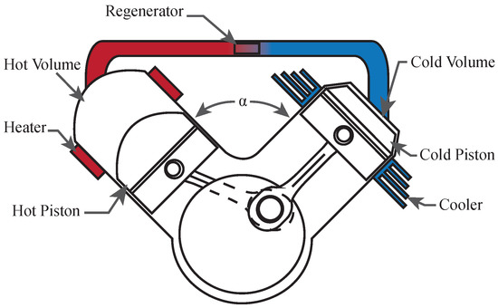
What is Stirling Engine - Types, Main Parts... - Mechanical Booster A Stirling engine is the type of engine in which unlike the internal combustion engine the heat energy source is external that can be achieved by various means like it can be achieved by burning fuel or it can be done by any electric means depending on the efficiency required, Working Principle.

Stirling engine pv diagram
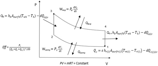
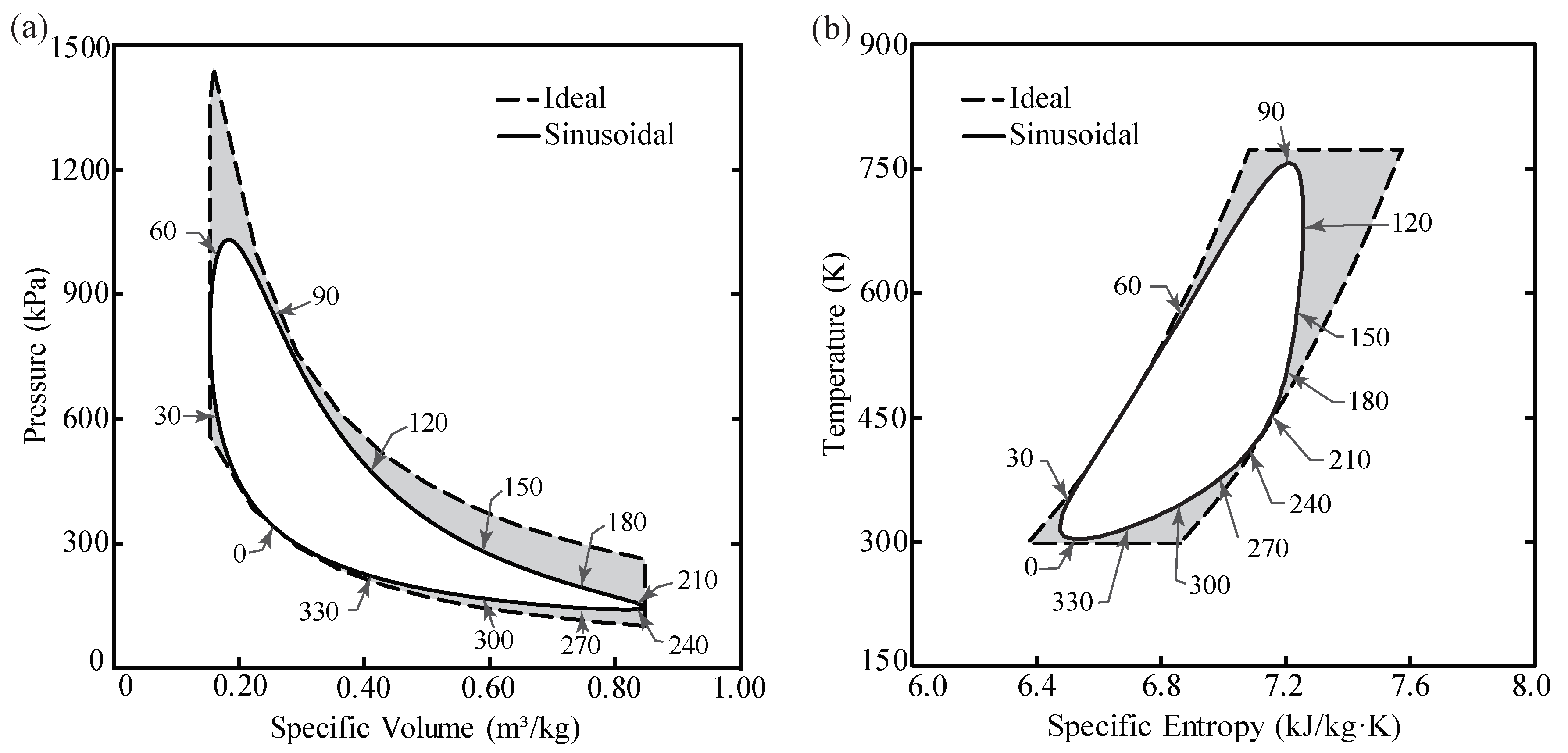
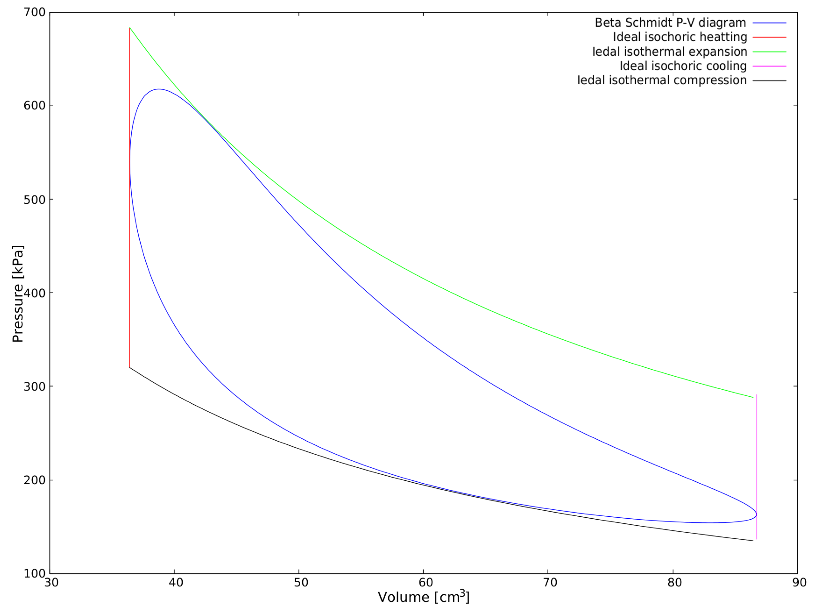
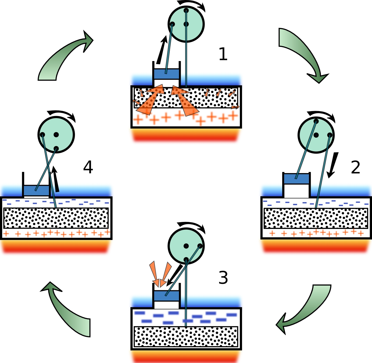
Commissioning and Performance Analysis of WhisperGen Stirling... Stirling engine based cogeneration systems have potential to reduce energy consumption and greenhouse gas emission, due to their high displacer lead or lag relative to the power piston, which can be non-sinusoidal and increase the area enclosed in PV diagram, resulting in greater power output. Stirling Cycle: Description of the Cycle of a Stirling Engine PV diagram of a real Stirling cycle; four angular positions of the crank of the machine that executes the cycle are indicated. The actual cycle can be represented on a pressure-volume (PV) diagram as a closed curve with a shape; this curve represents, with different values of pressure and temperature... Stirling Engine - Experimental Physics X-Athlon Stirling Engine. 3x3 Learning Objectives. Major ideas. See the provisional experiment guide in the attached document Stirling Engine v0_5.pdf . P2.6.2.4 The hot-air engine as a heat engine: recording and evaluating the pV diagram with CASSY http...
Stirling engine pv diagram. PDF Awomotive stirling engine engines-was envisioned. The Stirlingengine is this alternative. Invented in the early nineteenth century,the Stirling engine was regarded as a laboratory curiosityand was not taken seriously by the engineering com-munity What hampered its development? Thermodynamics Performance Analysis of Solar Stirling Engines Stirling engine in the 19th century was confined largely by the metallurgical possibilities and problems of the time. By these reasons, the engine was finally pushed back by newly developed internal combustion engines. The engine cycle is represented on PV and TS diagrams in Figure 1. The... (PDF) A Theoretical Improvement of a Stirling Engine PV Diagram The PV diagram of α-Stirling engine, Figure 1, is far away from an ideal PV dia-. gram Figure 2. The principle schema of the α-Stirling engine is shown in Figure 3. It could be observed that the engine has two crank rod mechanisms, one from. compression cylinder and the other for expansion cylinder. Stirling Engines - an overview | ScienceDirect Topics Stirling engines have a major advantage over other comparative processes in that the combustion here occurs in an external combustion engine. This minimizes the level of purification required for LFG compared with other utilization processes. Stirling engines can be successfully combined for CHP...
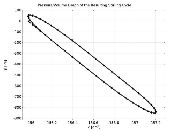
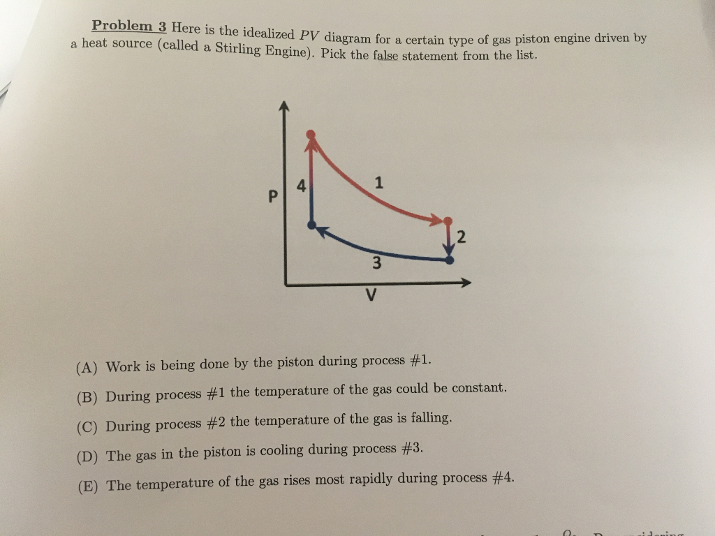
Stirling Engine Diagrams | PV Diagram of a Real Stirling Engine Stirling Engine Diagrams. Which Kind Of Diagram Are You Looking For? PV Diagrams are near the top. Stirling PV diagram typical of a real engine. Note the rounded corners. Image courtesy Comsol. The moving parts of all high-speed machines need to have a smooth motion, or the machine will tear... PDF Stirling engine Stirling engine, transparent Motor/generator unit Torque meter Chimney for stirling engine Meter f. stirling engine, pVnT Sensor unit pVn for stirl.eng. For other Stirling engines, the pV diagram may have a some-what different shape. Thus, for example, the surface is a func-tion of supplied thermal... PDF Stirling Engine Fabrication and Design A Stirling engine is an external combustion engine that creates work by utilizing a temperature gradient within a After looking at previous Stirling Engine MQP projects, our team made the decision of using a Beta configuration No work is done.2. Figure 9- PV and TS diagrams for Stirling Cycle. Stirling cycle - Wikipedia The classical Carnot heat engine. Category. v. t. e. The Stirling cycle is a thermodynamic cycle that describes the general class of Stirling devices. This includes the original Stirling engine that was invented, developed and patented in 1816 by Robert Stirling with help from his brother, an engineer.
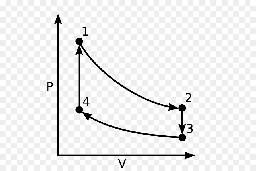
Heat Engine: Heat Engine Pv Diagram The Stirling Engine: The Heat Engine The Stirling Engine: The Heat Engine reversible heat engine depends only on the temperature change in the cycle. The Carnot 1. The pV diagram for an ideal Stirling cycle is shown in Fig (2). In our setup, two pistons ... PDF Stirling Engine Design Manual Stirling Engine Design Manual. Second Edition. William R. Maltini Martir)i Engineering Ricllland Washif_gtotl. Stirling. Engine Design Option Block Diagram. A wide variety of Stifling. engines have been manufactured. Heat Engines and Energy Conversion From the PV diagram this integral is equivalent to the area enclosed by the curve. Heat Engine Efficiency. The Ericsson engine, similar to the Stirling engine but using an open cycle, it is an external combustion engine with a regenerator which uses a double acting mechanical configuration. 32 Stirling Engine Pv Diagram - Wiring Diagram Database Stirling pv diagram typical of a real engine. Heat and temperature 2. Stirling cycle is one ideal cycle for the operation of stirling engine. Ultra low temperature difference james senft professor james senft. Note the rounded corners. The area inside the closed path on the pv diagram corresponds to the...
PDF Stirling Engine. Disadvantages Stirling Engine. How stuff works? In 1834 French engineer and physicist Emile Clapeyron stated the Ideal Gas Law as a combination of Boyle's and Pressure-Volume (P-V) diagram is one of the fundamental diagrams in the Stirling Cycle Theory. PV-diagram's area indicates a cooling work W...
Stirling Engine & PV-diagram - YouTube A Stirling engine is a type of a heat engine that runs when a temperature difference is applied between the top and bottom plates of the engine body.
A Stirling Engine for Automotive Applications The Stirling engine is a heat engine developed by Robert Stirling in 1816. It uses an external source of energy to heat the gas located inside a cylinder. 1. Theoretical Stirling cycle (PV and TS diagrams). A. Thermodynamic engine model. The model is based on the isothermal Schmidt analysis...
Stirling Engine Pressure Volume Diagram Low Temperature Differential The PV‐diagram of the Stirling engine is plotted on the computer monitor in real‐time. The top plate of the Stirling engine was modified to accommodate simple digital instruments from Venier to monitor the pressure and volume inside the engine.
STIRLING ENGINE PV DIAGRAM - Auto Electrical Wiring Diagram Stirling Engine Diagrams PV Diagram of a Real Stirling Engine. The P-40 Stirling engine See results only from stirlingengine Videos of Stirling Engine PV diagram Watch video2:30Stirling engine real-time PV diagram with Arduino Due and 7 inch TFT1 viewsOct 31, 2017YouTubeRalf...
Efficiency of Stirling Engine (Formula & Diagram) | Linquip Efficiency of Stirling Engine - A Stirling engine is a heat engine that operates by compressing and expanding air or another fluid (the working fluid) at The Stirling engine can be implemented in a variety of ways, although the majority of them fall under the category of reciprocating piston engines.
Figure 2: Pressure verses volume (PV-diagram) of the Stirling cycle. Now PV-diagram of the Stirling engine shown in Figure 2 can be examined in more detail. The key points are that during expansion along path 12 there is no temperature difference so that the change in internal energy dU = 0. From the first law of thermodynamics heat added from the hot reservoir is the...
PDF Stirling Engine Then the Stirling Engine's thermodynamic cycle is explained and the configuration is analyzed, which we do to make sure a further insight into the Stirling This diagram is feature of an alpha engine. The most important is to have the biggest grey area which represents the recuperated work during a cycle.
PDF Stirling Engine | 3-2. Work in PV-diagrams Work. PV-Diagrams. 3-0. What is a Stirling Engine? 6 components 1. Containers 2. Piston --- tightly sealed 3. Displacer --- large piston, loose 4. Crank When you place the Stirling engine on top of a cup of hot water, we are the following? (Assume that the engine is ideal.) (a) the PV-diagram (b) How...
PDF Heat Engine Efficiency | a) Sketch the cycle on a PV diagram. The Stirling Engine is an extremely versatile engine cycle where you only need a source of heat (or cold?), i.e. no boiling or combustion. Let's look at some actual Stirling Engines. PV Diagram for A Stirling Engine.
PDF 1.2 Stirling Engine Background Stirling Engine for Solar Thermal Electric Generation. by Mike Miao He. A dissertation submitted in partial satisfaction of the requirements for the Combining these waveforms gives a pV diagram, which is a trace of the thermodynamic cycle in terms of pressure and volume. The shape of the pV...
Stirling Engine - Experimental Physics X-Athlon Stirling Engine. 3x3 Learning Objectives. Major ideas. See the provisional experiment guide in the attached document Stirling Engine v0_5.pdf . P2.6.2.4 The hot-air engine as a heat engine: recording and evaluating the pV diagram with CASSY http...
Stirling Cycle: Description of the Cycle of a Stirling Engine PV diagram of a real Stirling cycle; four angular positions of the crank of the machine that executes the cycle are indicated. The actual cycle can be represented on a pressure-volume (PV) diagram as a closed curve with a shape; this curve represents, with different values of pressure and temperature...
Commissioning and Performance Analysis of WhisperGen Stirling... Stirling engine based cogeneration systems have potential to reduce energy consumption and greenhouse gas emission, due to their high displacer lead or lag relative to the power piston, which can be non-sinusoidal and increase the area enclosed in PV diagram, resulting in greater power output.













Comments
Post a Comment