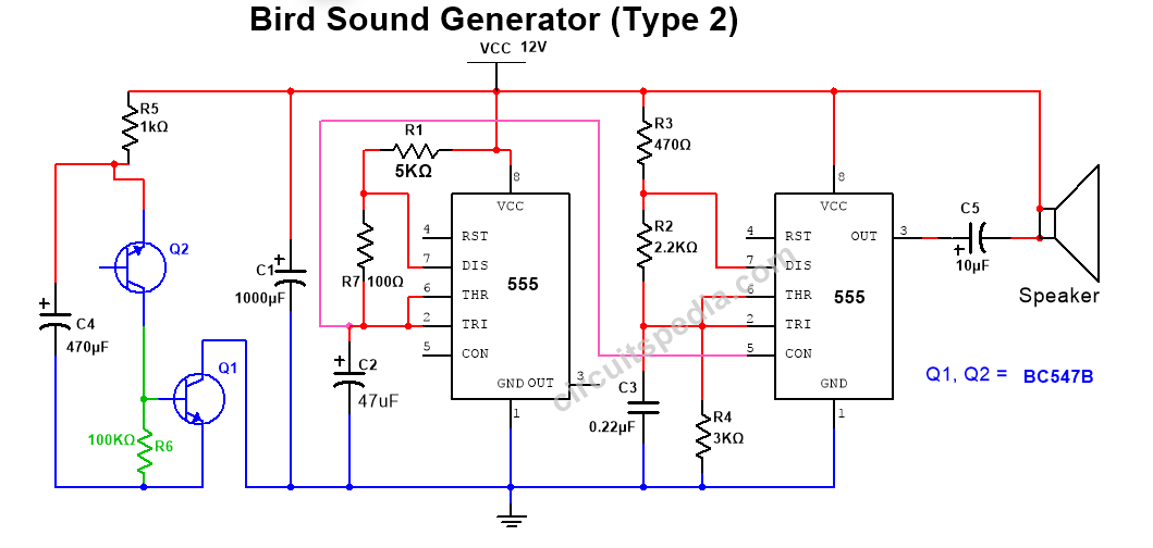
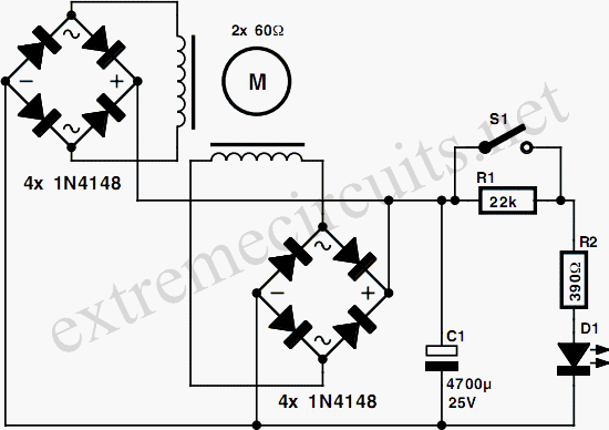
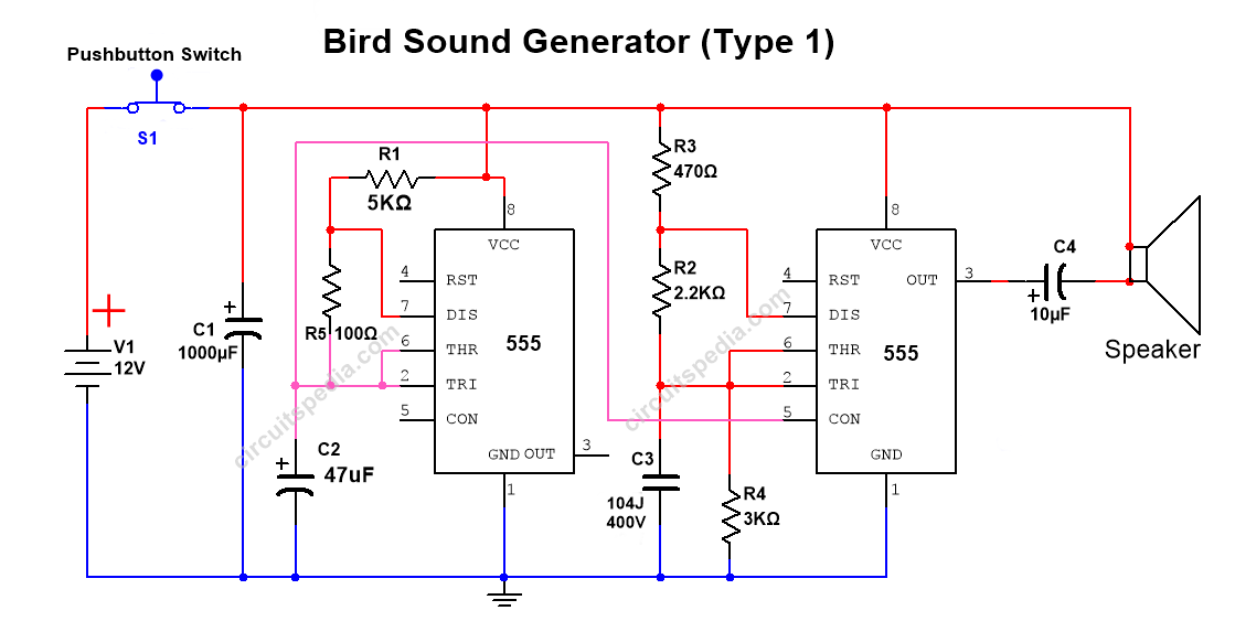
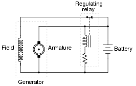
40 generator circuit diagram
portable generator wiring diagrams - Wiring Diagram and ... Small Sel Generators Wiring Diagrams Briggs And Stratton Power Products 030552 01 7 500 Watt Portable Generator Parts Diagram For Wiring 80010737wd Small Sel Generators Wiring Diagrams China 3p 630a Ats Wiring Diagram Automatic Transfer Switch For Portable Generator Changeover Small Sel Generators Wiring Diagrams Wiring Diagram For Kohler Generator - Wiring Diagram Line Wiring Diagram For Garden Tractors With A Delco Remy Starter Generator Isavetractors. Ariens 915055 005000 009999 Zoom 1944 19hp Kohler 44 Deck Parts Diagram For Wiring. Starter Generator Voltage Regulator Wiring Wheel Horse Electrical Redsquare Forum. Figure 3 2 Interconnection Diagram Transfer Switch To Generator.
Generator Wiring Diagram and Electrical Schematics Step 2: Determine Your Generator Plug Type and Amperage First you have to figure out what type of amperage and plug type we are working with. You only want to do this on a generator with a big round plug. This will provide 220V (in the US) and power both sides of your breaker box. You will see the amperage written near the plug.

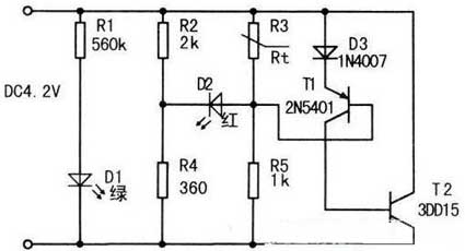
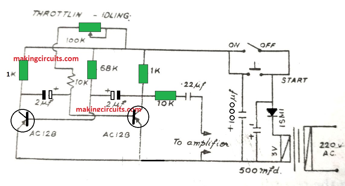
Generator circuit diagram
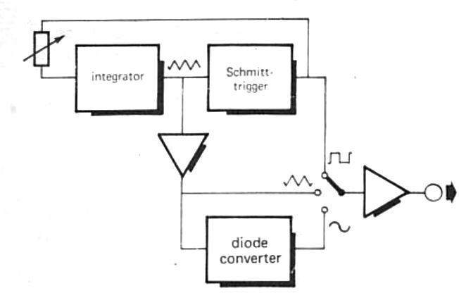
Triangular wave generator using opamp. Circuit diagram ... The circuit diagram is shown in the figure below. Circuit diagram The square wave generator section and the integrator section of the circuit are explained in detail below. Square wave generator The square wave generator is based on a uA741 opamp (IC1). Resistor R1 and capacitor C1 determines the frequency of the square wave. Fuelless Generator Circuit Diagrams - wiringall.com In the plans of the generator, the circuit diagram starts from one metal plate placed in the air (as high as possible) and the second one in the ground. The two metal plates are connected to the capacitors using a simple set of wires: each wire is connected to each side of the capacitor. Schematic/Wiring Diagram Generator - Zuken US Schematic/Wiring Diagram Generator. E3.Wiring Diagram Generator automatically generates schematics/wiring diagrams for development, service and after-sales. It can also be used to migrate and create standardized diagrams from legacy systems. After defining the diagram placement and routing rules, schematic/wiring diagrams are generated ...
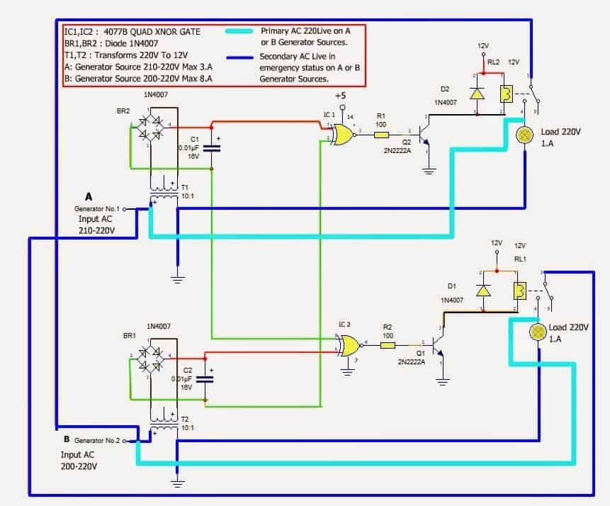
Generator circuit diagram. Complete circuit diagram of high power ultrasonic generator Circuit diagram of high power ultrasonic generator (1) Figure 1 is the schematic diagram of the system circuit, which is composed of grid filter boat, power frequency rectification and filtering, high frequency inverter, high frequency transformer, ultrasonic transducer and PWM circuit. The principle of the main circuit is shown in Figure 2. AC Generator - Working Principle, Parts, AC Generator Diagram AC generator is a machine that converts mechanical energy into electrical energy. The AC Generator's input supply is mechanical energy supplied by steam turbines, gas turbines and combustion engines. The output is alternating electrical power in the form of alternating voltage and current. single phase brushless generator wiring diagram - Wiring ... Small Sel Generators Wiring Diagrams Simplified Diagram Of A Brushless Synchronous Machine With Hsbds Scientific China Single Phase Brushless Generator Circuit Diagram Automatic Voltage Regulator Avr As480 Voltage Regulator For Brushless Synchronous Generator With Harmonic Excitation Winding Mastervolt Single Phase Ac Alternators automatic changeover switch circuit diagram for generator ... Complete Circuit Diagram Of Automatic Phase Changeover Switch Scientific Ats5070 Generator Automatic Transfer Switch China Generator Automatic Changeover Switch Wiring Diagram Transfer Briggs And Stratton Power Products 040438 01 17 000 Watt Home Standby Generator With 200 Amp Ats Ge Parts Diagram For Wiring Transfer Switch
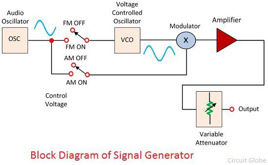
Circuit Diagram - A Circuit Diagram Maker A free, user-friendly program for making electronic circuit diagrams. Get Started Design Create diagrams visually by placing components with your cursor. Extend the built-in functionality with custom components. Render Export circuits as scalable vector images, or convert to a selection of other formats. Simulate Diesel Generator Wiring Diagram Pdf - U Wiring Wiring between the generator and the load must be used according to the power of generator. Electrical Wiring Diagram Of Diesel Generator wiring diagram is a simplified within acceptable limits pictorial representation of an electrical circuitIt shows the components of the circuit as simplified shapes and the knack and signal associates along ... 3 Phase Generator Wiring Diagram - IOT Wiring Diagram Circuit Diagram Of The Generator Connected With Three Phase Resistive Scientific. Electerical Engineering And Tecnolgy Manual Changeover Switch Wiring Diagram For Portable Generator 8 43 00 Am 3 Comments Today I Writing About As You Know That. Generator Voltage Changes 277 480 3 Phase 120 240 Vac Single. 7 Wires 3 5kw Three Phase Generator Avr ... Tone generator Circuit Diagram - Engineers Garage Tone generator Circuit Diagram. The tone generator's function is to produce different frequency sine wave for each digital word applied to its input. This project allows the computer to sweep the instrument under test through the desired frequency range. It can be adapted to create a Morse code circuit, by adding a switch to the output.
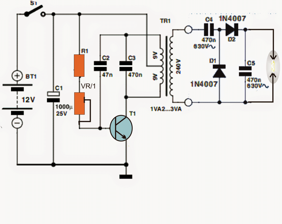
Complete circuit diagram of high voltage pulse generator ... High voltage pulse generator circuit diagram 1: Equivalent circuit of main discharge circuit of high voltage pulse generator. Among them, s is the controllable switch, C1 is the capacitor bank capacitance, R1 is the loss resistance at the input end of the high voltage transformer, L1 and L2 are the primary inductance of the high voltage transformer, K is the coupling coefficient, C2 is the ... Tone generator circuit Diagrams Archives - Circuit Diagrams LM2931-5.0 is a Random Noise Generator too Schematic Circuit Diagram The low dropout voltage regulators from the LM2931 series are not just useful for powering microcontroller systems — they can… Read More » Wise Tech September 2, 2018 0 153 Simple RF Noise Source Schematic Circuit Diagram Square Wave Generator : Circuit Diagram and Its Advantages There are two parts of a triangular wave generator circuit. One part generates the square wave, and the second part converts the square wave into a triangular waveform. The first circuit consists of an op-amp and a voltage divider connected to the op-amp's non-inverting terminal. The inverting terminal is grounded. Schematic/Wiring Diagram Generator - Zuken US Schematic/Wiring Diagram Generator. E3.Wiring Diagram Generator automatically generates schematics/wiring diagrams for development, service and after-sales. It can also be used to migrate and create standardized diagrams from legacy systems. After defining the diagram placement and routing rules, schematic/wiring diagrams are generated ...
Fuelless Generator Circuit Diagrams - wiringall.com In the plans of the generator, the circuit diagram starts from one metal plate placed in the air (as high as possible) and the second one in the ground. The two metal plates are connected to the capacitors using a simple set of wires: each wire is connected to each side of the capacitor.
Triangular wave generator using opamp. Circuit diagram ... The circuit diagram is shown in the figure below. Circuit diagram The square wave generator section and the integrator section of the circuit are explained in detail below. Square wave generator The square wave generator is based on a uA741 opamp (IC1). Resistor R1 and capacitor C1 determines the frequency of the square wave.














Comments
Post a Comment