39 cnc breakout board wiring diagram
PDF User Manual of 5Axis Breakout Board - LinuxCNC 5 Axis Breakout Board Interface Adapter ECG--SAVEBASE 4 2. Setup Units: Choose "MM's" in Config->Set Default Units for Setup 3. Click "Config"->"Ports and Pins" on Main Interface. 5 Axis Breakout Board Interface Adapter ECG--SAVEBASE 5 4. Enter in "Port Setup and Axis Selection" to set "Port#1" and "Kernel Speed" shown as below. 5. PDF Mach3 Breakout Board with Relay & Spindle Control Mach3 Breakout Board with Relay & Spindle Control DC- DC+ 5V Power Supply AC-N AC-L GND. Engine Configuretion... Pots & Pins Motor Outputs Input Signals Output Signals Spindle Setup Mill Options ... Mach3 BoB with Spindle and Relay Wiring Diagram (April 2017) Created Date:
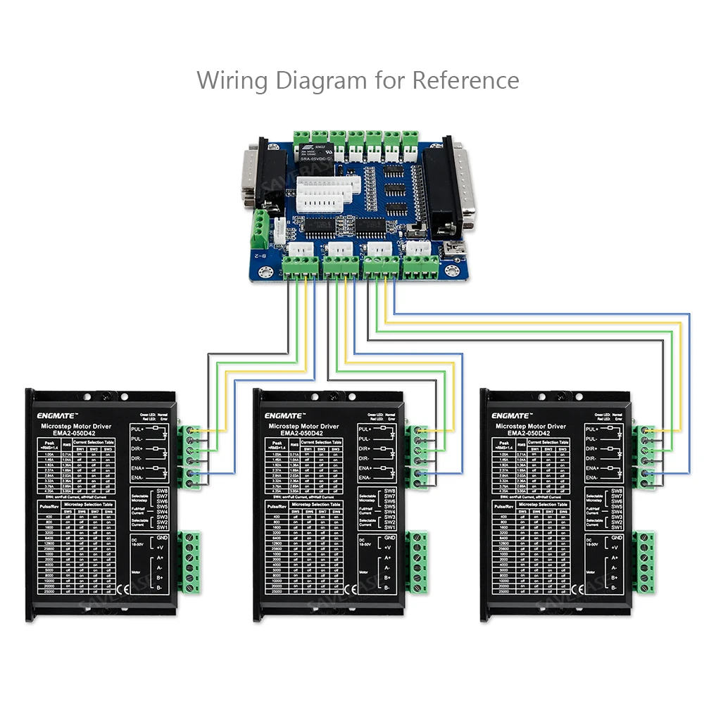
PDF User Manual of 5Axis Breakout Board - Communica South Africa 5 Axis Breakout Board Interface Adapter 3 4 Wiring Diagram for Reference 5 MACH3 Software Settings Note: The settings on MACH3 below is in condition that breakout board and stepper drivers are connected in common anode. 1. Check whether the MACH3 driver is installed correctly.

Cnc breakout board wiring diagram
PDF 5axis breakout board-EN - Solectroshop 5axis_breakout_board-EN.pdf Author: jan Created Date: 11/15/2017 10:26:48 AM ... Mach3 Breakout Board Wiring - schematron.org Picture 1. Board PDF press the link below. mach3 5 Axis CNC Breakout Board V 3. Step 1. Digital Driver CCK to Power supply. step 2. step 3 you need to wire the driver with ST-V3 breakout board. C10 Breakout Boards with digital cnc driver and CCK Diagram Wiring schematic. PDF User Manual of 5Axis Breakout Board 5 Axis Breakout Board Interface Adapter 4 2. Setup Units: Choose "MM's" in Config->Set Default Units for Setup 3. Click "Config"->"Ports and Pins" on Main Interface. 5 Axis Breakout Board Interface Adapter 5 4. Enter in "Port Setup and Axis Selection" to set "Port#1" and "Kernel Speed" shown as below. 5.
Cnc breakout board wiring diagram. Cnc Breakout Board Wiring Diagram - schematron.org 5 axis breakout board MACH KCAM4 EMC2 driver interface adapter KK01 DataSheet: CW + KK01 Wiring Diagram DataSheet. 5 Axis CNC Breakout Board Interface Users Manual sales@schematron.org schematron.org This document describes the basic functionality. Do you have a wiring diagram for your breakout board and ... It is not necessary for a wiring diagram for the breakout board to the SuperPID controller since you are only going to connect two wires from the breakout board output terminals of your choosing to the SuperPID controller. The only thing remaining is to configure Mach3 so that the spindle control section serves as the SuperPID controller. Cnc Breakout Board Wiring Diagram The Routout CNC 25 Way D Breakout has many uses including for CNC retrofitting / robot control. It allows you to wire to the parallel port / LPT port using screw terminals, this makes wiring limit / sensing switches to you CNC .Cnc Breakout Board Wiring Diagram : 33 Wiring Diagram Images - Wiring Diagrams | diagramweb.netNeed Help! 5 Axis Breakout Board Driver Wiring Example - YouTube Example wiring of stepper drivers to 5 axis breakout board with Mach3 info.
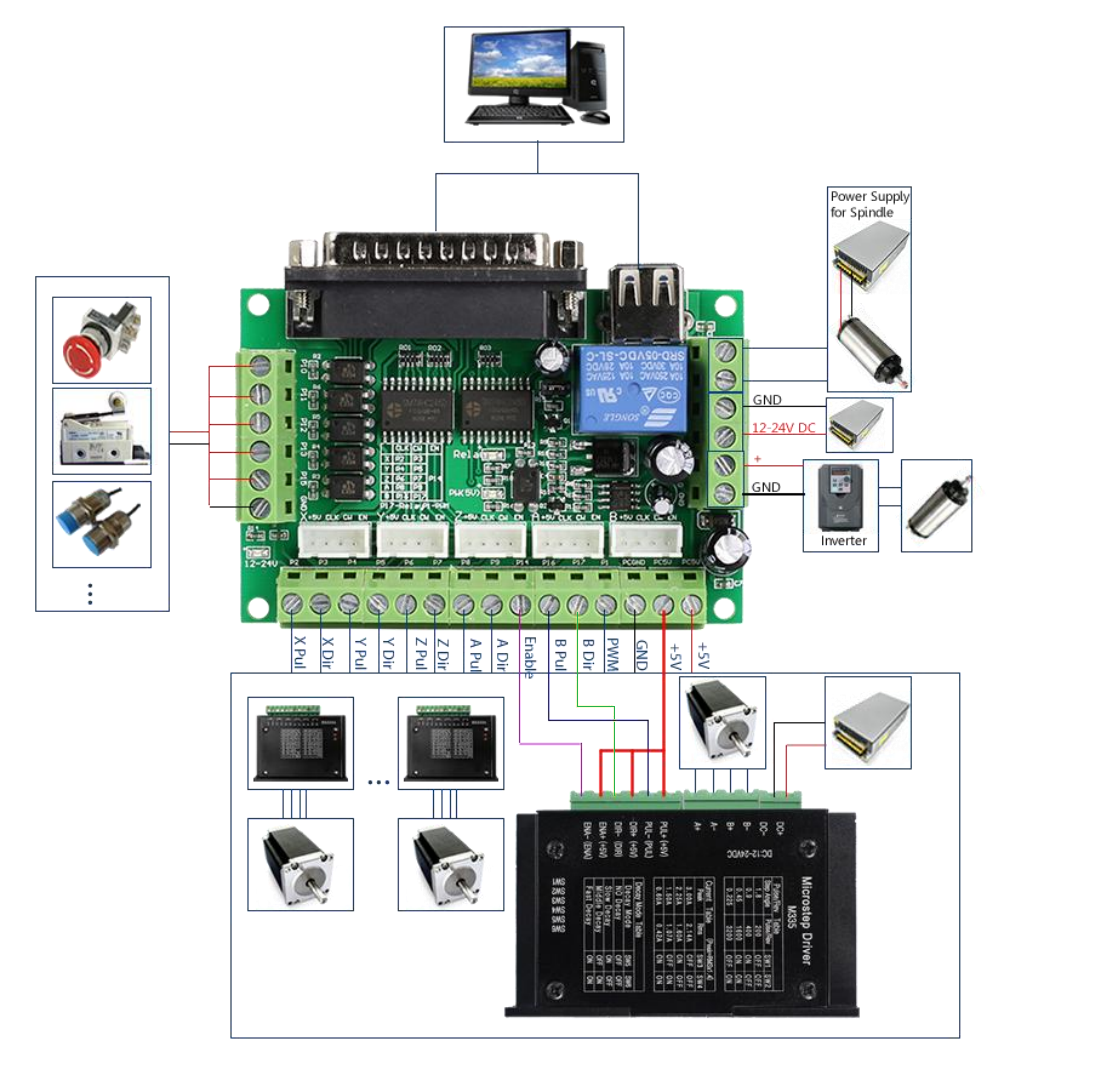
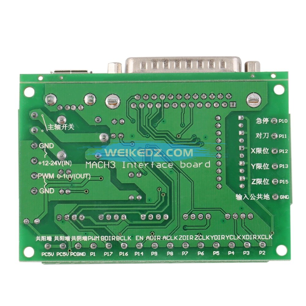
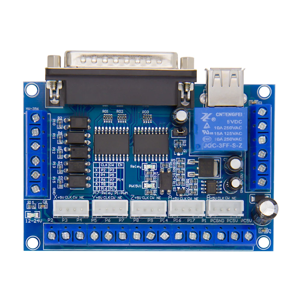
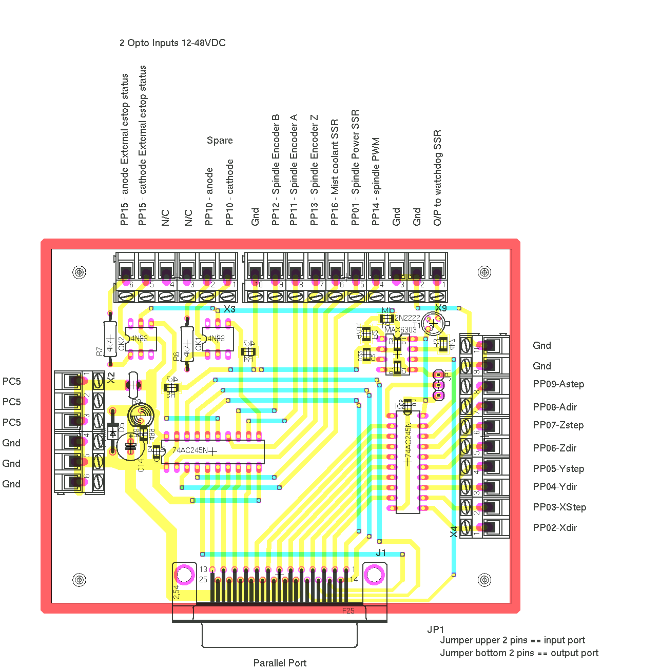
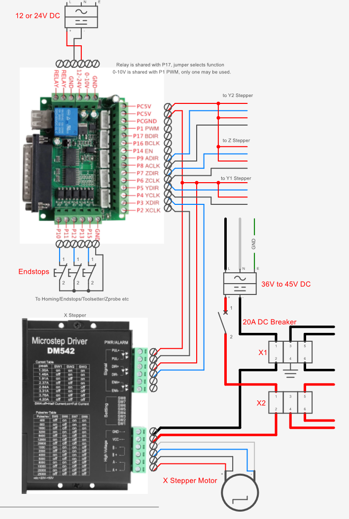
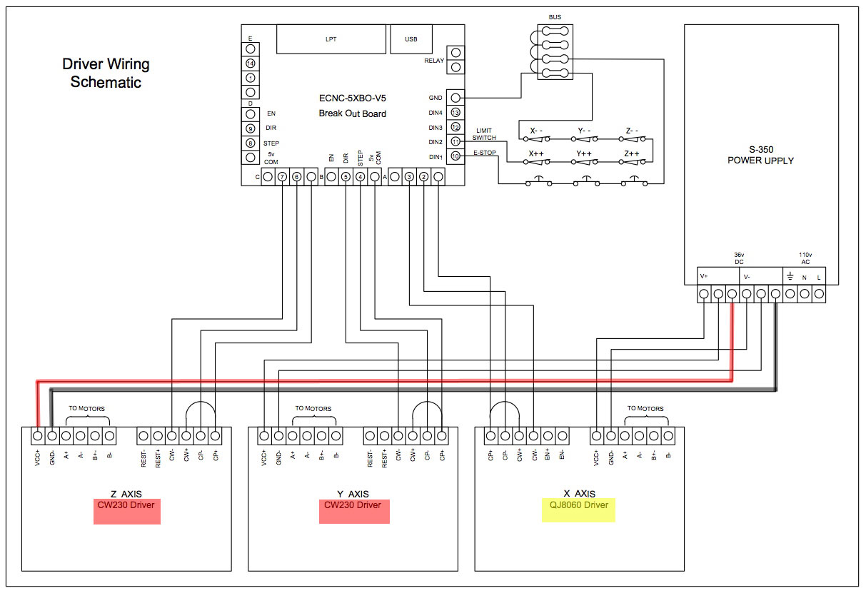
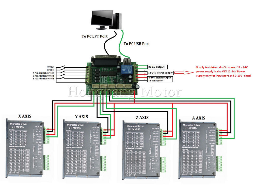
CNC Electronics and Wiring - Build Your CNC The wiring of the parallel breakout board from the output terminals to the driver digital pulse (step pulse) and direction lines are explained. The new parallel breakout board appears a bit different, but the process of wiring and testing is the same. Go to the new parallel breakout board to get more information and the wiring diagram. Complete Wiring Diagram - CNC 6-Axis Interface Breakout ... Complete Wiring Diagram - CNC 6-Axis Interface Breakout Board with Relay and Spindle Control Posted on June 9, 2017 February 10, 2019 by Tyler @ Design Concepts The breakout board that I'm referring to is . Schematics - CNC Controller Technical Manual Future Signal Inputs: The signal inputs on the CRP850-00E board are designed for NPN signals, which close signal to ground. The input signal terminals provide ports for direct wiring of limit switches, touch plate, and auxiliary signals. Replicated Outputs: These are 5V digital outputs which can be used to drive relays with 5V coils or 5V logic level devices. Cnc Mini Mill Control Box Wiring - bg 0852 cnc control box ... Cnc Mini Mill Control Box Wiring - 17 images - cnc spindle wiring diagram auto electrical wiring diagram, grbl cnc control with arduino 1 youtube, chuy n i cnc rf 45 m y phay ph n 1 m y kh c cnc mini, the cnc blog control box,
PDF 1. Functions and Features - STEPPERONLINE 5 Axis CNC Breakout Board Interface Users Manual sales@stepperonline.com C. Motor turning: Its relate to the screw pitch and the excitation mode of the motor driver. The below diagram setting is base on 5mm screw pitch and excitation mode is 1/8 mircostepping. Steps per is means how many steps it need for moving 1 mm. PDF Manual for Breakout Board Hg08 - Cnc4you CONNECTION DIAGRAM FOR LIMIT SWITCH AND BREAKDOWN SWITCH Input port pins are opto isolated and use isolated 5 Volts (VCC) for up to 1000V isolation thus helping to protect your PC or control electronics. You can connect up to 5 lines with limit switches, emergency Stop switch, reset etc. you can connect sensors for robots etc. PDF C10 - BIDIRECTIONAL BREAKOUT BOARD Rev. 10 C10 - BIDIRECTIONAL BREAKOUT BOARD Rev. 10 Sample wiring using to board to connect drivers, e-stop, limit switches, and a relay to start your spindle +5VDC POWER SUPPLY TOGGLE SWITCH TO ENABLE THE SYSTEM MANUALLY You can connect the limit switches in series using NC (Normally Closed) switches. Cnc Breakout Board Wiring Diagram Awesome | Wiring Diagram ... Cnc Breakout Board Wiring Diagram Awesome-Allowed in order to my own weblog, with this period I'm going to teach you in relation to cnc breakout board wiring diagram. And after this, this is the initial impression: C10 Breakout Board Wiring Collection from cnc breakout board wiring diagram , source:visithoustontexas.org
Lada Git karşılaşmak usb cnc breakout board - dorscheltires.com
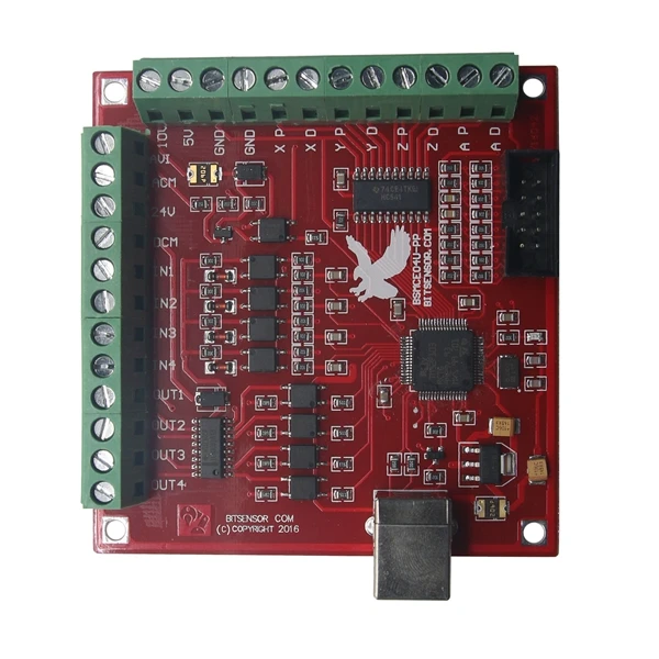
PDF C11g Wiring Diagram - Stepper Motor |CNC Router 5V EN GND 1 2 COM 3 4 COM 5 6 COM 7 8 COM 9 14 16 GND 17 12v 0-10v GNDA NO V-IN NC NO V-IN NC NO V-IN NC GND GND 5V 5V 5V 10 5V 11 12 13 15 GND C11G Multifunction CNC Board Outputs Outputs Analog Output IEEE 1284 Jumper 1-2 Compatible 2-3 Not Compatible

Eletric Wiring Diagram. | Download Scientific Diagram
c10 breakoutboard wiring diagram - The Blog The C10 Breakout Board Gets An Update! And it kinda freaked me out. If you're used to the C10 breakout board used for CNC router machines, plasma cutters or laser cutters, you're used to it being a single sided board with all components on the top. Well, they did a change that freaked me out and it made me think they sent the board unfinished.
help!!! I need of wires ST-V2 (alias KK-01) breakborad and ...
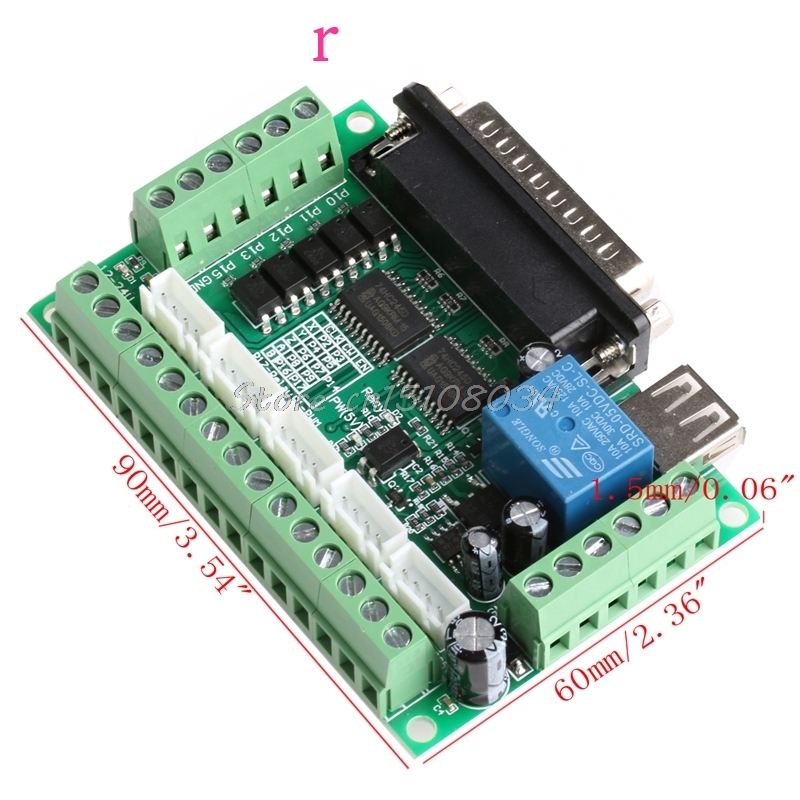
CNC Breakout Board: Complete Guide and Reference Parallel CNC Breakout Boards connect to your PC's parallel port and convert those signals to screw terminals which you may then use in point-to-point wiring to connect up the rest of your system. These are the most commonly used type of breakout board. They're simple, and relatively inexpensive. They have a few drawbacks.

Breakout board KK01 CNC Stepper Motor 5 Axis with Relay
CNC wiring diagram - YouTube 18.4K subscribers Subscribe In this video, I explain how my cnc router is wired using a wiring diagram that I drew that is specific to my machine. You can download a copy of this wiring diagram by...

CNC Controller – Control plate – My Workshop
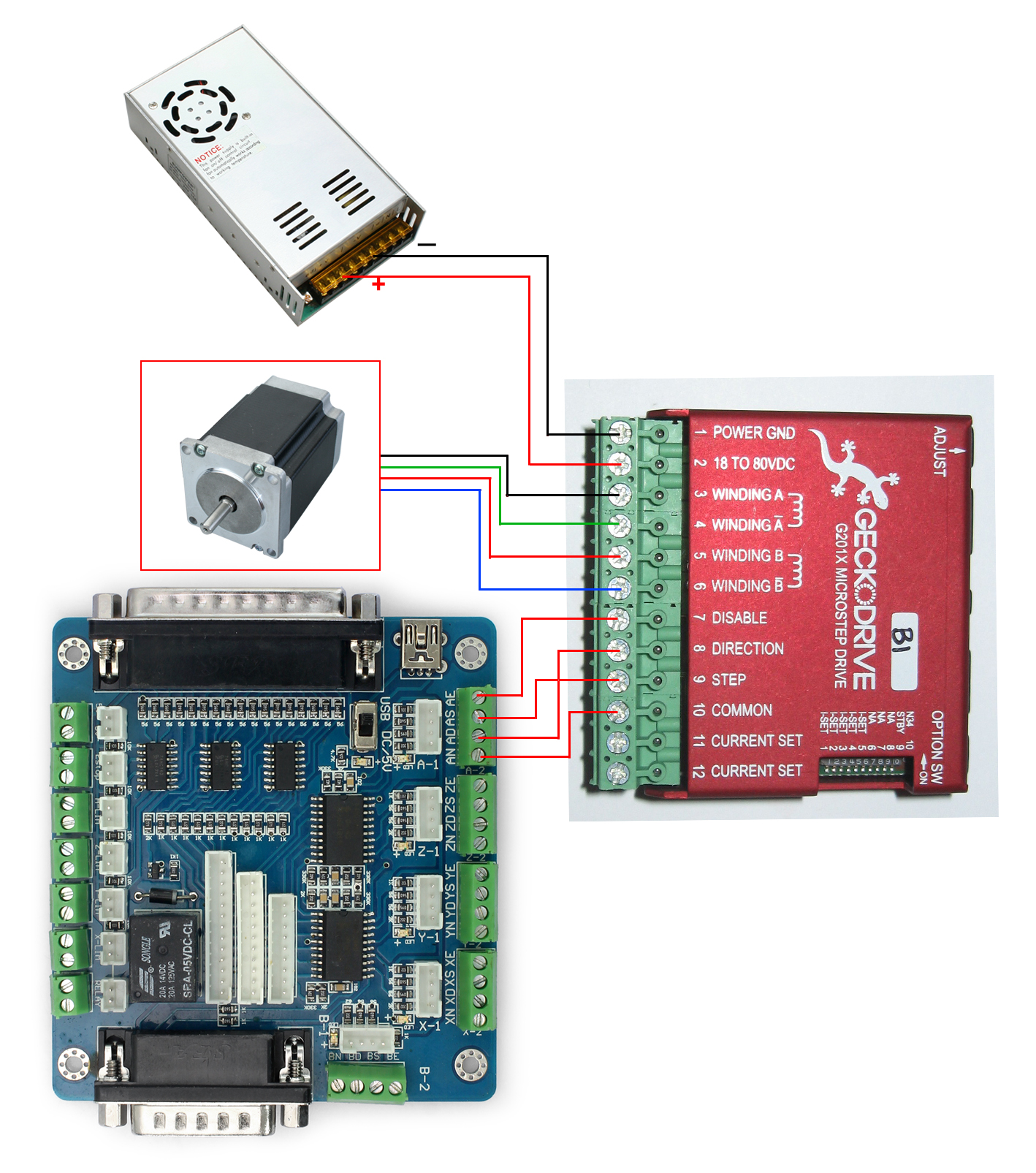
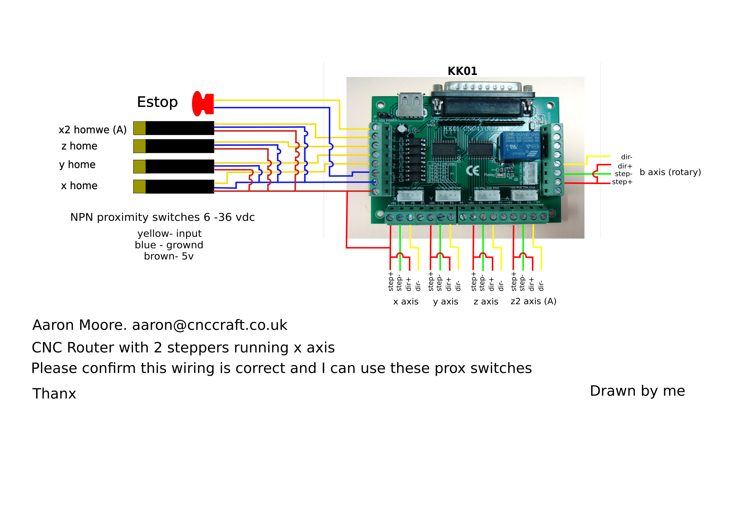
PDF CNC Wiring Diagram CWD556 + KK01 Breakout Board Noise generated by Plasma cutters etc. will require filtering to allow stable operation of your CNC or automated machinery. Wiring Diagram for Power Supplies V- + POS=V C -V = COM= GND L N L N L N Switch Mode PSU's 48 Volt With Our Low Inductance Nema 23 Stepper Motors Page 3 X AXIS WIRING DIAGRAM YEL BLK WHT BRN RED BLU ORG GRN
LinuxCNC Breakout Board | PrintNC Wiki
PDF Stainsmart Breakout ST-V3 Board Model (1) - Askjerry Title: Stainsmart Breakout ST-V3 Board Model (1) Author: jrutherford Created Date: 8/5/2015 8:21:16 PM
Mach3 breakout board Original 5 Axes CNC Breakout Board w ...
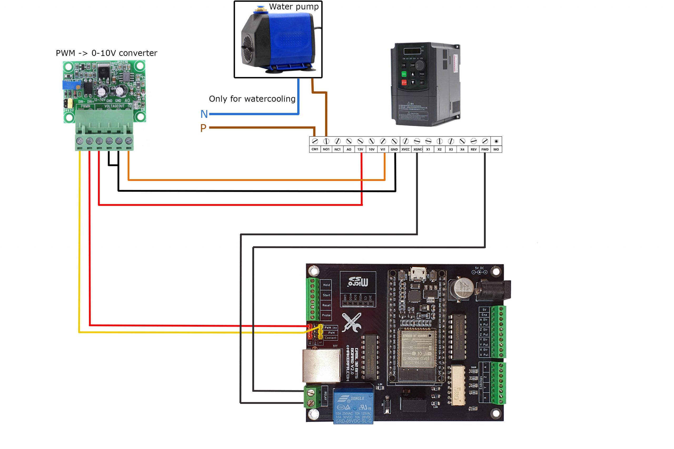
Using output board for spindle control - Planet CNC GND signal from output board will be connected to this input. Connect output pins of controller with input pins of output board: Connect output board with VFD's control inputs: Wiring diagram below illustrates how relays and varying voltage output are connected with VFDs control inputs so that we achieve on/off, direction and speed control:
GRBL 32bits board V2.0 – MakerFr
Arduino 3 Axis Cnc Shield Stepper Board Wiring Diagram Pololu - Minimal wiring diagram for connecting a microcontroller to an A laser CNC Dashboard control board USB CNC 3 axis stepper motor controller. 3-Axis CNC/Stepper Motor Shield for Arduino breakout board, with this shield and ArduinoUno/Mega, you can build all kinds of .
5 Axis Cnc Interface Adapter Breakout Board For Stepper Motor ...
PDF Manual 6 Axis CNC Interface Breakout Board Manual ... Safety Notes: The control board is DC power electronics of the designed to accept ONLY. Ensure connections are made correctly that the positive and negative before power oning the unit. Incorrect wiring will cause damage to the board. The control board is o not conductive objects an open circuit ...
Kaufen Sie 5 Achsen CNC Breakout Board Schnittstellenkarte ...
PDF C11G- MULTIFUNTCION CNC BOARD Rev. 9 - CNC4PC These are the steps for replacing a potentiometer: 1. Measure the voltage difference between P1 and P3. Make sure it measures under +12vdc. 2. Fine tune the analog output to the output voltage you got from step 1. 3. Connect the ground from the analog output to the ground of the potentiometer (P1). 4.
breakout board
PDF User Manual of 5Axis Breakout Board 5 Axis Breakout Board Interface Adapter 4 2. Setup Units: Choose "MM's" in Config->Set Default Units for Setup 3. Click "Config"->"Ports and Pins" on Main Interface. 5 Axis Breakout Board Interface Adapter 5 4. Enter in "Port Setup and Axis Selection" to set "Port#1" and "Kernel Speed" shown as below. 5.
MACH3 5 Axis CNC Breakout Board For Stepper Motor Driver CNC ...
Mach3 Breakout Board Wiring - schematron.org Picture 1. Board PDF press the link below. mach3 5 Axis CNC Breakout Board V 3. Step 1. Digital Driver CCK to Power supply. step 2. step 3 you need to wire the driver with ST-V3 breakout board. C10 Breakout Boards with digital cnc driver and CCK Diagram Wiring schematic.
Need Help! 5 axis breakout board wiring PLease :'(
PDF 5axis breakout board-EN - Solectroshop 5axis_breakout_board-EN.pdf Author: jan Created Date: 11/15/2017 10:26:48 AM ...
Instruction of Breakout Board
5 Axis CNC Breakout Board With Optical Coupler For MACH3 ...
DIY Parallel Port Breakout Board
Cnc Usb Mach3 100khz Breakout-board 4 Achse Schnittstelle ...
Wiring the PrintNC | PrintNC Wiki

Mach 3 USB Breakout Board 4 Axis Controller – CNC Online SA

Longs Motor 4 Axis CNC Kit - The Nerdy Talk
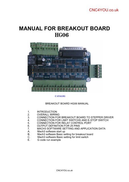
manual for breakout board hg06 - CNC4YOU for your CNC Parts ...

Damon's Random Ramblings: CNC Rebuild Wiring Diagram Version 1
5-axis CNC Breakout board User Manual
User Manual of 5Axis Breakout Board

XHC Mach3 Motion Control Card Breakout Board 2MHz | NVCNC.NET
BOB and SMD Setup | RainyDayMagazine
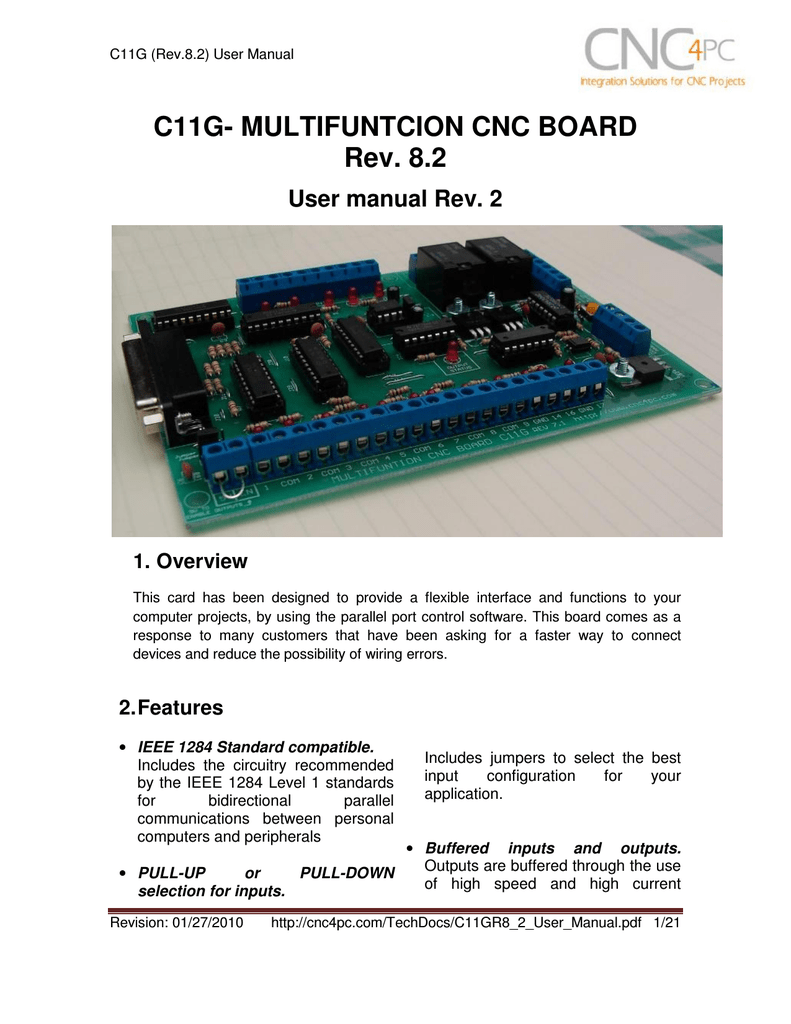
C11G- MULTIFUNTCION CNC BOARD Rev. 8.2 User manual Rev | Manualzz
5-axis CNC Breakout board User Manual
help!!! I need of wires ST-V2 (alias KK-01) breakborad and ...
Help with configuration for new Breakout board - LinuxCNC
SAVEBASE CNC 5 Achsen USB Breakout Board Interface Adapter ...

Breakout Board eBay Kleinanzeigen

THC Installation Step by Step - General Discussion - Langmuir ...

5 Achsen Mach3 Stepper Motor Controller Board Breakout Board ...
IndustryArena Forum
CNC Breakout Board: Complete Guide and Reference
User Manual
CNC Electronics and Wiring

Currency € Euro £ Pound Sterling $ US Dollar My Account My ...


Comments
Post a Comment