39 cnc wiring diagram
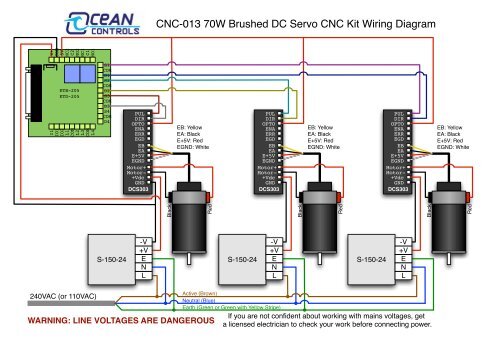
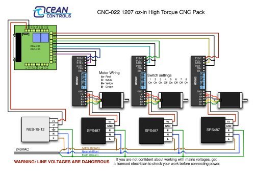
Using this wiring kit, you really just need to plug in the motors, tape or otherwise secure the connection and go.. There are now two wiring choices. I highly recommend you start with the series wiring kit. The dual kit adds complexity with that complexity you gain accuracy and precision. Wiring Diagram For Stepper Motor Plug Scientific. Stepper motor wiring diagram computer cnc shield 2 motors router listrik cara kontrol dengan 3 axis milling machine tb6560 driver with a4988 arduino to tb6600 for nema23 china 42shd3401s cd rom pibot electronics 0 kits ushine mach3 usb kit 3pcs 1 control l298n single two phase hybrid nema 23 datasheet specs mill drive plug 7a db25 breakout ...
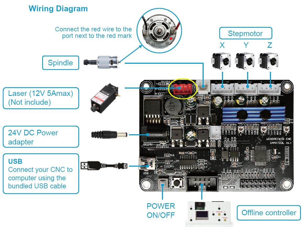
The offline cnc controller system features high reliability, high precision, low noise, and easy operation. The standalone cnc controller can be linked with 5 axes, and has multi-micro line segment forward control algorithm, which can realize five-axis linear interpolation and five-axis multi-micro multi-line segment continuous interpolation, and has continuous line engraving control, power ...

Cnc wiring diagram
STB5100 Wiring Diagram v2.1 for MACH3 Software Download. STB5100 Wiring Diagram v2.1 for Drufel CNC Software Download - Stepper Motors / Stepper Drivers. Stepper Motor - 23HD86001Y-21B Download. Stepper Motor - 23HD56001Y-21B Download. TB6600-Stepper-Motor-Driver-BM3D-v1.1 Download CCK to ST-V3 Breakout Board. Picture 1. Board PDF press the link below. mach3 5 Axis CNC Breakout Board V 3. Step 1. Digital Driver CCK to Power supply. step 2. step 3 you need to wire the driver with ST-V3 breakout board. C10 Breakout Boards with digital cnc driver and CCK Diagram Wiring schematic. On this website we will show you step by step ... By using this website, or viewing any videos here, you agree to waive all liability of BuildyourCNC, or any personnel associated with the making of this website. Step 1: Wiring Instructions for CNC Electronics Step 1. Step 2: CNC Machine Electronics Wiring Step 2. Step 3: CNC Machine Electronics Wiring Step 3. Final Step.
Cnc wiring diagram. Designed to work as an attachment to the Torchmate 4000 series CNC plasma tables, this machine is plug and play and interfaces seamlessly with your existing machine. This machine can cut 1.5 in to 6 in schedule 40 pipe - and can handle a maximum pipe length of 7 ft. Cnc Endstop Wiring Diagram 17.04.2019 17.04.2019 7 Comments on Cnc Endstop Wiring Diagram CNC shield V schematron.org https:// schematron.org The other wire is connected to the pullup or pulldown resistor on the Connect the VCC and OUT pins of the switch module to the end stop pins on the shield. operation of your CNC or automated machinery. Wiring Diagram for Power Supplies V-+ POS=V C-V = COM= GND L N L N L N Switch Mode PSU's 48 Volt With Our Low Inductance Nema 23 Stepper Motors Page 3 . X AXIS WIRING DIAGRAM YEL BLK WHT BRN RED BLU ORG GRN A+ A- B+ B-VCC GND P1 P3 P2 VCC GND VCC GND VCC GND V C C G N D PSU 5V Regulated >500mA Band Saws CNC Mills (KX1/KX3) Coolant Systems Cutting Tools HiTorque Lathes, Bench 8.5x16/8.5x20 (SC4) HiTorque Lathes, Mini 7x12/7x16 (SC2) HiTorque Mills, Bench (SX2.7) HiTorque Mills, Large Bench (SX3.5) HiTorque Mills, Micro (SX1P) HiTorque Mills, Mini (SX2) Lathes, 10x21 (C6) Lathes, 8x12/8x14 Lathes, Micro 4x5 (C0) Lathes, Micro 6x10 (C1 ...
In this video, I explain how my cnc router is wired using a wiring diagram that I drew that is specific to my machine. You can download a copy of this wirin... CNC Control Panels and CNC Pendants. This page is simply a roundup of CNC panels and CNC pendants I've found on the Internet so you can see what kinds of features others have incorporated. confidencbd. C. shamim akhter. shamim 22000. Cnc Router Table. Diy Cnc Router. Wood Router. Here are the simplified wiring diagrams for the RS-CNC. 1- Power diagram:. The colors of the wires of the stepper motors may vary from one manufacturer to another, check the documentation of your motors to know which color correspond to the wires A +, A-, B +, B- DIY CNC Router: If you have any interest in purchasing a kit version of this machine please click the above button and complete the form so that I can gauge the level of interest.This instructable will show you how to construct a CNC Router that will allow you to…
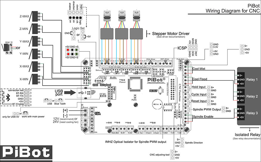
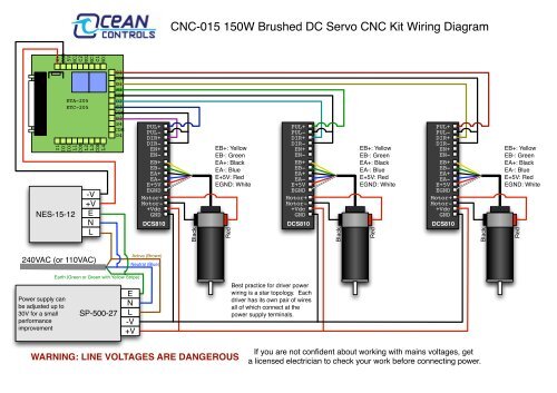
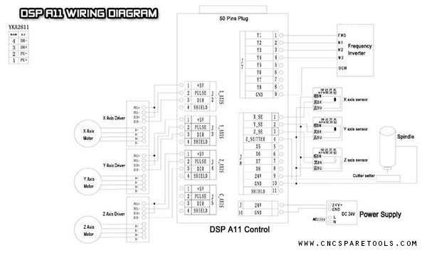
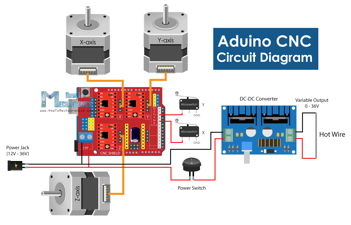
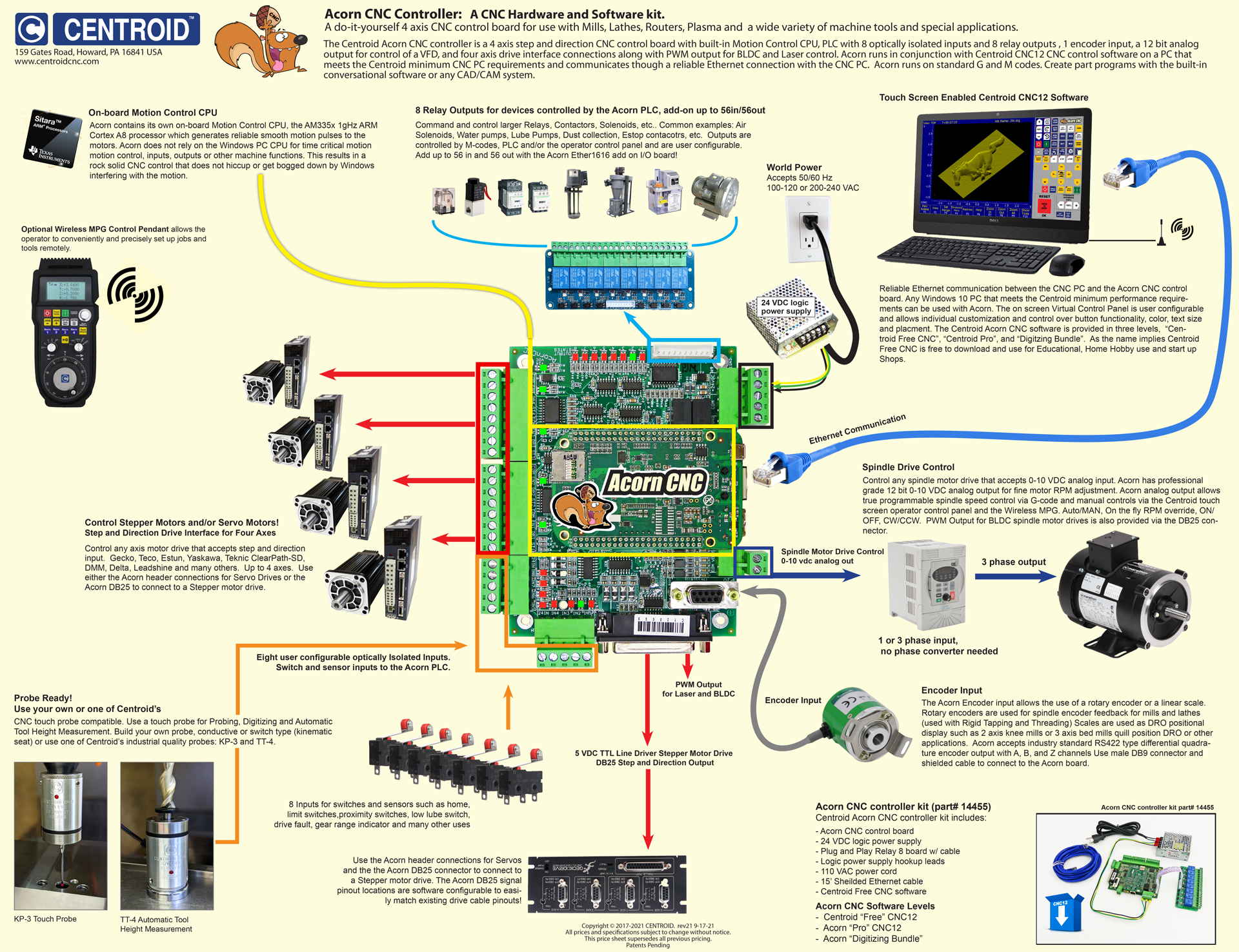
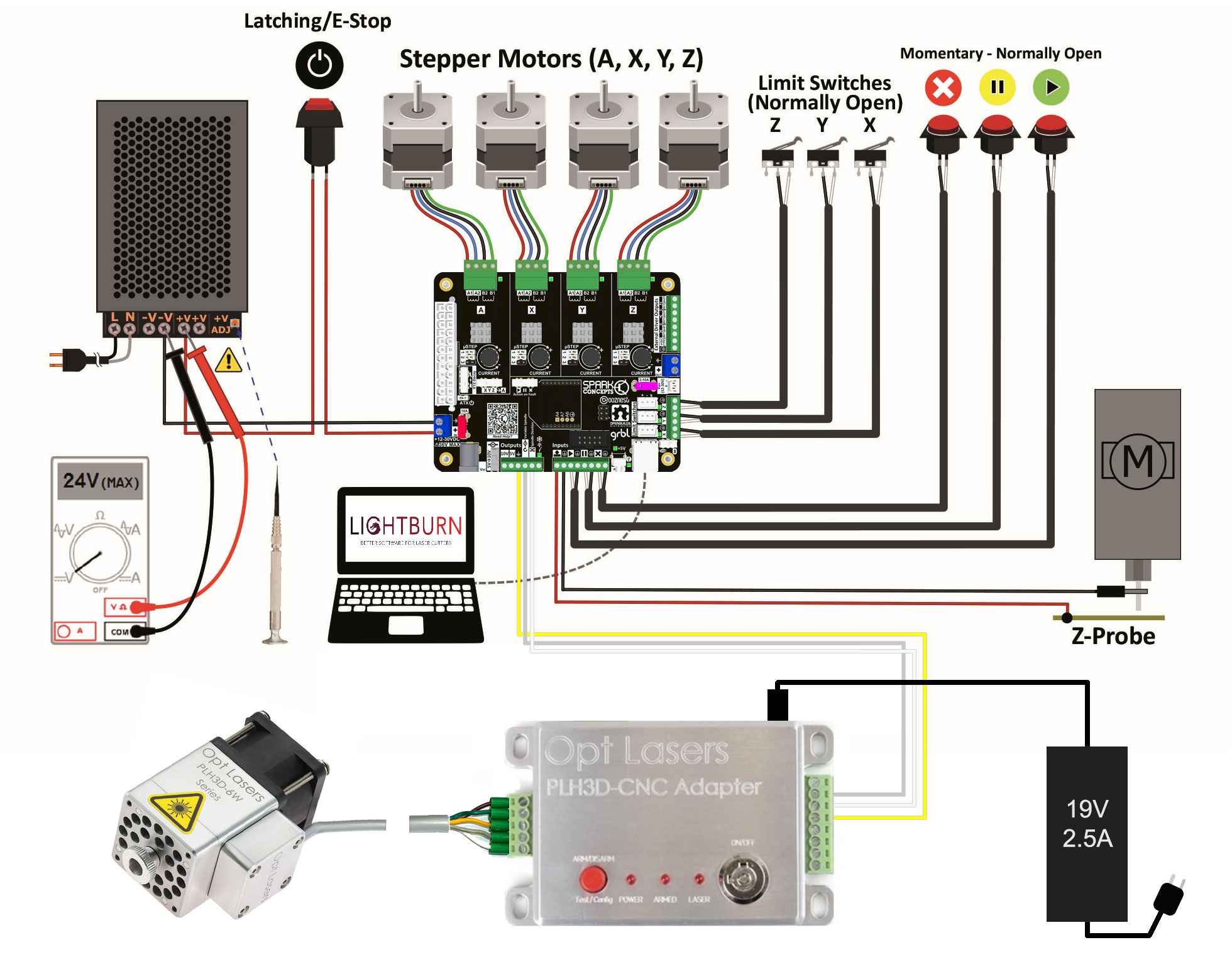
Assortment of cnc router wiring diagram. A wiring diagram is a streamlined conventional photographic representation of an electric circuit. It shows the elements of the circuit as streamlined shapes, and the power and also signal connections in between the tools. Cnc Wiring Diagram- wiring diagram is a simplified within acceptable limits pictorial representation of an electrical circuit.It shows the components of the circuit as simplified shapes, and the capacity and signal associates amid the devices. A wiring diagram usually gives counsel approximately the relative slant and union of devices and terminals upon the devices, to urge on in building or ... The Big Easy Driver is a stepper motor driver board for bi- polar stepper motors up to The basic wiring diagram is shown below in Figure 3. Professional CNC Kit For Arduino, Kuman grbl CNC Shield + Uno Board + rampe . Pololu - Minimal wiring diagram for connecting a microcontroller to an A laser CNC Dashboard control board USB CNC 3 axis ... Arduino Uno Cnc Wiring Diagram. I keep seeing nice clean clear arduino schematics like this one. Make Wiring Diagram Arduino-Allowed in order to my personal blog site with this moment Well teach you in relation to make wiring diagram arduino. Dht11 With I2c Lcd And Arduino Uno Wiring Diagram Schematic Arduino Humidity Sensor Arduino Humidity ...
I made a whole series about building my own CNC router last year and I still get many questions about the electronics, so I decided to make a better video ab...
2.3 START/PAUSE/ESTOP Switch Wiring This USB port is the standard USB A-type. A 50cm USB extension cord with installation plug is supplied with the controller. See sketch diagram picture 2-5 for reference. 2.4 USB Wiring Picture 2-3 START/PAUSE/ESTOP/COM interface Picture 2-4 Circuit drawing of START/PAUSE/ESTOP/COM
The wiring of the parallel breakout board from the output terminals to the driver digital pulse (step pulse) and direction lines are explained. The new parallel breakout board appears a bit different, but the process of wiring and testing is the same. Go to the new parallel breakout board to get more information and the wiring diagram.
6 Axis CNC MACH3 Engraving Machine Interface Breakout Board USB PWM from cnc breakout board wiring diagram , source:aliexpress.com. So, if you would like obtain all these magnificent pics about (Cnc Breakout Board Wiring Diagram. Awesome), just click save icon to store these photos for your pc. They're ready for transfer, if you like and want ...
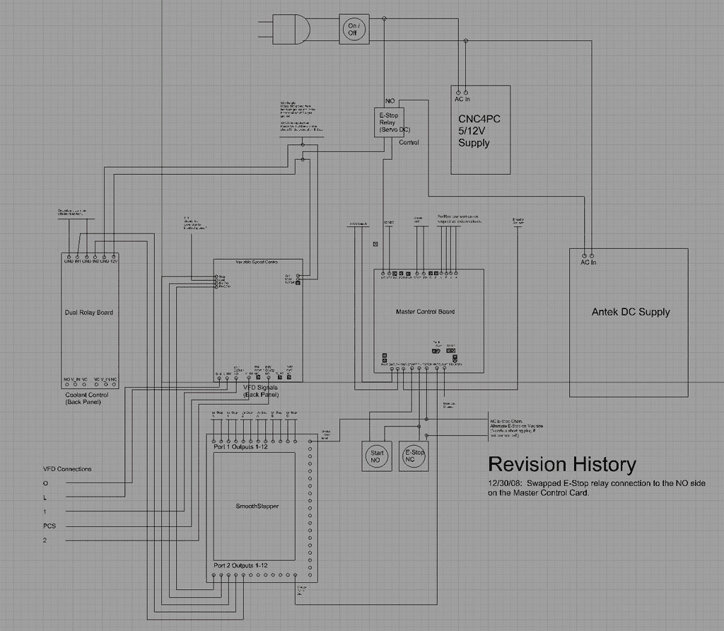
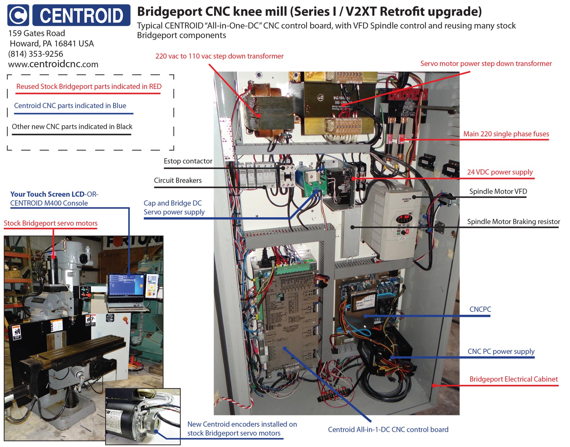
The CNC wiring diagram shown in this page is created using Mechanical Desktop Version 6 and the wiring digram is showing you the very basic CNC wiring circuit diagram. Basically this CNC machine controlled by the CNC machine controller which consists of a CNC servo drive to control all the electrical parts such as axes servo motors, coolant ...
The serial port on the Powermax is a 5-pin male connector (also called a Phoenix connector). The wiring diagram below shows the signals and how they would connect to a 9-pin connector on the CNC. The 9-pin connector shown below is used on Hypertherm EDGE® Pro CNCs. Be sure to check the serial port on your CNC for the correct pin assignments.
CNC Manual / Fadal / Fadal Wiring Diagram Manual. Fadal Wiring Diagram Manual. Views: 56170 . Continue with reading or go to download page. Read Download. Recommended. Fadal VMC Fanuc Maintenance Manual. 303 pages. Fadal VMC Fanuc 18i MB5 Operator Manual. 57 pages. Fanuc 16i-MB Operator Manual.
MACH3 Breakout Board SUPPORT CNC SYSTEM. To be high-impedancestate Hi-Z when USB is connected. 221 USB port As the Figure 2-2 showed Marked No. According to Sainsmart 4 Axis Mach3 Usb Cnc Motion Controller Wiring Diagram you will find just four wires used in the cable. Make sure you board is connected to the PC via USB cable.
May 07, 2016 · Although these pictures don’t show anode/cathode on the pins, it is visible in the tool, and I wanted to get it right. So I edited the part, changed the pin wiring, and saved it as a new part. This was all very straightforward. Then I decided I wanted to have the pins be labeled A, B, C so that it would show up in the schematic view.
13.08.2016 - See 8 Best Images of CNC Schematic Diagram. Inspiring CNC Schematic Diagram template images. Limit Switch Wiring Diagram CNC Limit Switch Wiring Diagram CNC Controller Schematic CNC Wiring-Diagram Remington 700 Trigger Diagram
operation of your CNC or automated machinery. Wiring Diagram for Power Supplies L N L N L N Switch Mode PSU's and Toroidal LIVE (BROWN) NEUTRAL (BLUE) Earth wire bolted to mounting Plate. Uo 50VAC OUTPUT 50VAC OUTPUT BLU BRN WHT WHT CW6060AC CWD872 CW885 UK 2 HSS86 RED = RED BLU = BLUE BLK = BLACK BBRN = BBROWN
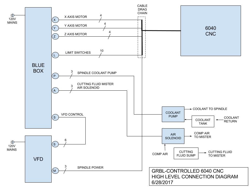
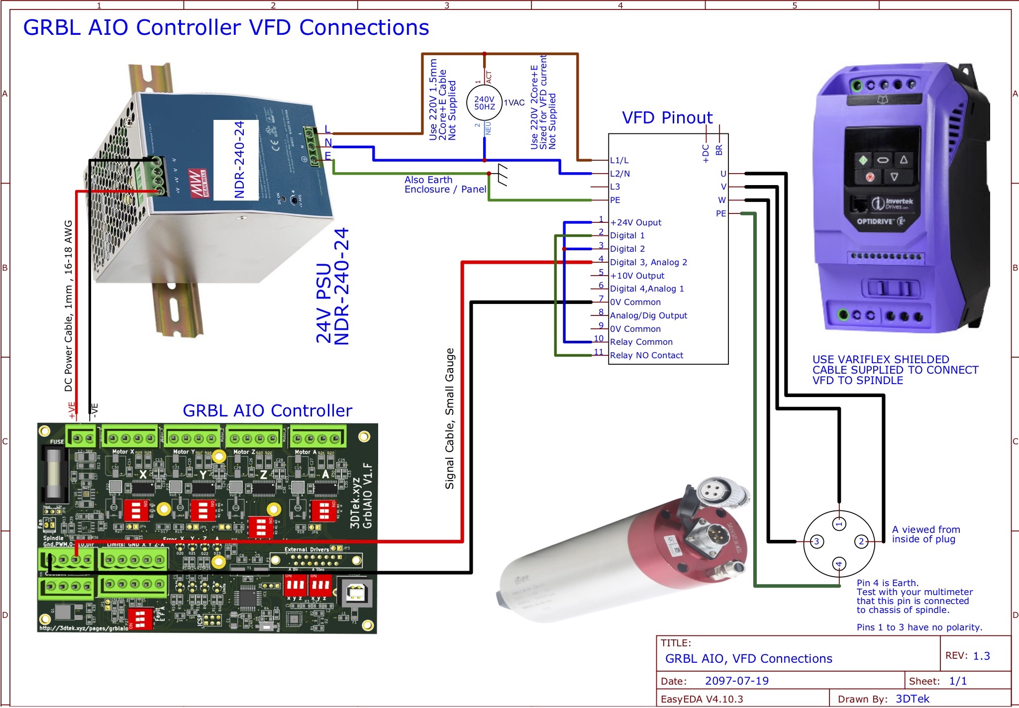
Grbl Wiring Diagram. The wiring is simple but there is no indication if one of the switches is The schematic of the end sensor board which uses optocouplers. INSTRUCTION MANUAL - GRBL CNC CONTROLLER. Version: .. outputs on the GRBL board in the following diagram. to clone the Y axis.
Two CNC cables are also provided in the plasma cutter box; a torch ON/OFF cable and a THC port wiring cable. Older versions of the Razorweld 45 CNC have a 4-pin Torch firing port and a 2-pin voltage divider port.
The system is intended for CNC control of milling machines, routers, lathes, flame, plasma, laser/water jet cutters, and other ... Power Supply Wiring Diagram For GPIO4D L i v e 1 1 0 V (n o t i n c l u d e d) N e u t r a l 1 1 0 V ((n o t i n c l u d e d) G r o u n d (1 1 0 V n o t i n c l u d e d) V 3 (-1 2 V) + 5 V + V 2 V (+ 1 2 V) C O M m ...
Get Cnc Router Wiring Diagram Sample. Variety of cnc router wiring diagram. A wiring diagram is a streamlined conventional pictorial representation of an electric circuit. It shows the components of the circuit as simplified forms, and also the power and also signal links in between the devices. A wiring diagram usually provides info about the ...
By using this website, or viewing any videos here, you agree to waive all liability of BuildyourCNC, or any personnel associated with the making of this website. Step 1: Wiring Instructions for CNC Electronics Step 1. Step 2: CNC Machine Electronics Wiring Step 2. Step 3: CNC Machine Electronics Wiring Step 3. Final Step.
CCK to ST-V3 Breakout Board. Picture 1. Board PDF press the link below. mach3 5 Axis CNC Breakout Board V 3. Step 1. Digital Driver CCK to Power supply. step 2. step 3 you need to wire the driver with ST-V3 breakout board. C10 Breakout Boards with digital cnc driver and CCK Diagram Wiring schematic. On this website we will show you step by step ...
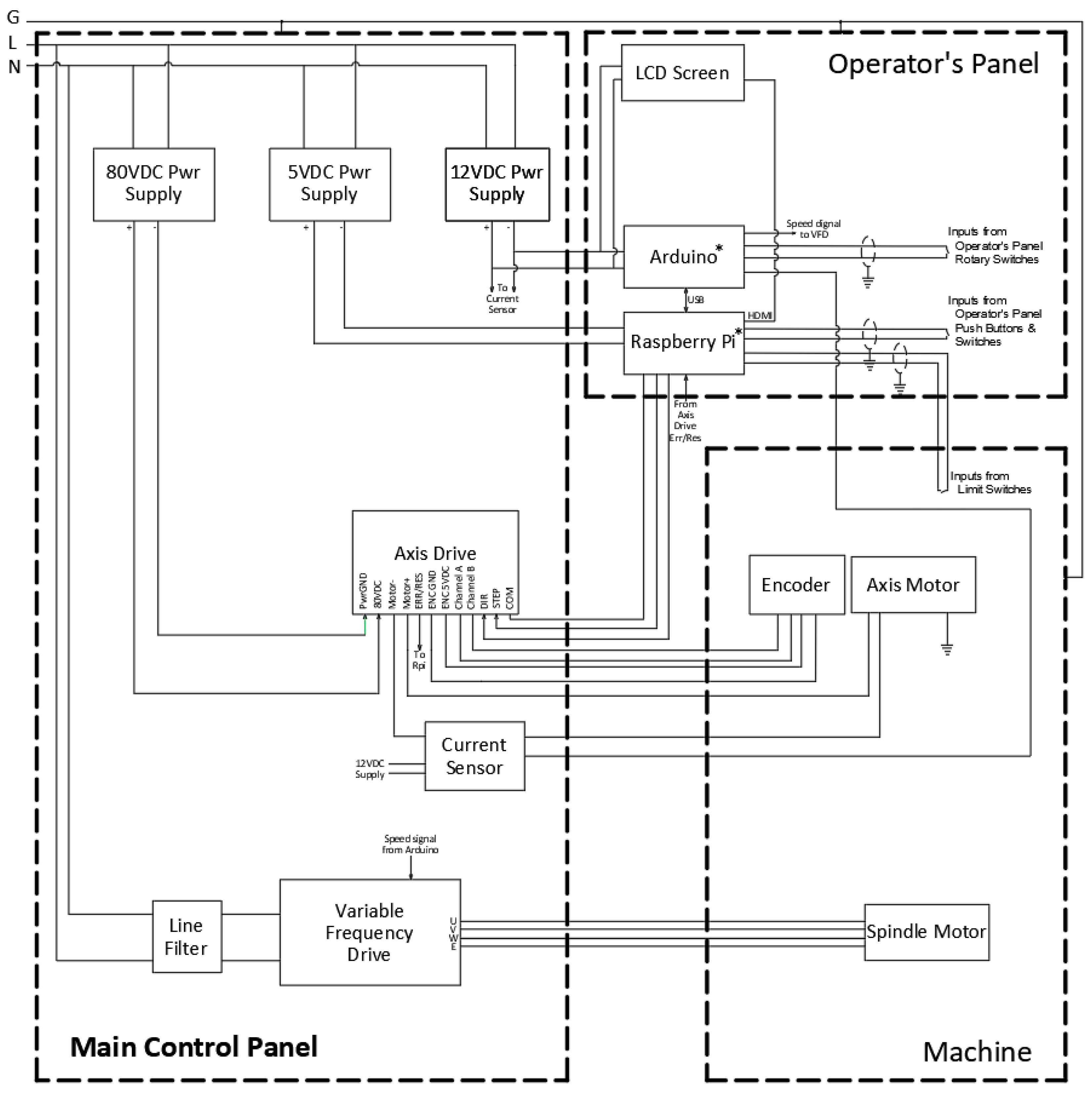
Applied Sciences Free Full Text Step Nc Compliant Intelligent Cnc Milling Machine With An Open Architecture Controller Html
STB5100 Wiring Diagram v2.1 for MACH3 Software Download. STB5100 Wiring Diagram v2.1 for Drufel CNC Software Download - Stepper Motors / Stepper Drivers. Stepper Motor - 23HD86001Y-21B Download. Stepper Motor - 23HD56001Y-21B Download. TB6600-Stepper-Motor-Driver-BM3D-v1.1 Download













Comments
Post a Comment