40 paragon defrost timer wiring diagram
Good day, ladies and gentlemen. For your consideration, I'd like to present what I believe to be the safest and mod-friendly wire diagram for a custom ESC installation, in this case 24V. I believe I have wired in two separate fail safes, both of which can be triggered by driver and one of which can be triggered remotely if desired. My wiring diagram can be used for 12V or 24V installations but for 12V you need to basically correctly choose your relays, ESC, and put the 12V LEDs in parallel so t... If there is a timer, set it for longer than the estimated firing time.. 8145-20ex - Paragon Electric 8145-20ex Timer Module. Defrost · Paragon 9145-00 Programmable Defrost Control Commercial.. Diagram 8145 20 Paragon Defrost Timer Wiring Full Version Hd Quality ... 120VAC 24-Hour/ 7-Day Electronic Timer Module Intermatic timer instructions ...
30.09.2021 · N. Korea's parliamentary session. This photo, released by North Korea's official Korean Central News Agency on Sept. 30, 2021, shows Kim Song-nam, director of the International Department of the ruling Workers' Party's Central Committee, who was elected as a member of the State Affairs Commission, the country's highest decision-making body, during …
Paragon defrost timer wiring diagram
Jun 22, 2021 · Paragon 8145 20 defrost timer wiring diagram. It reveals the elements of the circuit as simplified forms and also the power and also signal connections between the tools. Collection of paragon defrost timer 8145 20 wiring diagram. 8047 20 208 240 for electric heat defrosting auxiliary contact models 50 hz available open open closed 4 110 min. Dec 09, 2018 · Then timer outputs can control 3-phase power using 3-phase contactors Contactor below is 3 phase with V coil http: Link below is for Paragon commercial box-type defrost timers http: I cant seem to find a wiring diagram on how to wire this correctly Link below has wiring diagrams and wiring manuals for V http: According to information from ... Wiring Diagram. Models , and E -. the wiring diagram chosen. (Default setting B). 14 AWG OR LARGER WIRES RATED AT LEAST ⁰C. LISTED . and Electric Heat. •. •. •. Series Specifications. Uni-Line Applications and Wiring Diagrams. MECHANICAL.Paragon - V Defrost Timer - Designed for commercial freezers and refrigerators, Paragon commercial ...
Paragon defrost timer wiring diagram. SThe Subaru EJ201 and EJ202 were 2.0-litre horizontally-opposed (or ‘boxer’) four-cylinder petrol engines. Replacing the EJ20 Phase I engine, the EJ201 and EJ202 were members of Subaru’s EJ Phase II engine family which introduced newly designed … Paragon 8141-20 - 208/240V Defrost Timer - Designed for commercial freezers and refrigerators, Paragon commercial defrost controls provide automatic defrost capability. They accommodate various types of defrost systems including electric defrost heaters, hot gas and compressor off cycle. Time initiated, temperature or pressure terminated High ... The Latest Paragon® Defrost Timer • Universal Defrost Timers (UDT) • Works with multiple voltages • Removes built up of ice and frost • Easy to install • Simple to program • Part 9145-00 temp terminated • Part 9045-00 time terminated • Available as mechanism only without case - Add "M" to end of part number The Paragon® 8000 Series Auto Voltage Defrost Timer is designed for commercial freezers and refrigerators. Paragon Defrost Controls have provided reliable automatic defrost capability for decades. They accommodate various types of defrost systems including electric defrost heaters, hot gas, and compressor off cycle.
Paragon 00 Wiring Diagram Defrost Timer Circuit Evaporator. The Paragon® Series Auto Voltage Defrost Timer is designed for commercial freezers Wiring Diagrams. AV. AV Heavy-duty steel case with electrical knockouts in the sides, Specifications. Operating Voltages: or / VAC, 60 Hz HEATER. Oct 12, 2018 · I cant seem to find a wiring diagram on how to wire this correctly Link below has wiring diagrams and wiring manuals for V Paragon - /V Defrost Timer - Designed for commercial freezers and refrigerators, Paragon commercial defrost controls provide automatic defrost capability. Paragon 20 Wiring Diagram - Wiring Diagram Pdf Free Paragon 20 wiring diagram in addition defrost timer wiring diagram further diagram model tr timer along with paragon defrost control 26x also defrost Read More At ... Description: Paragon Defrost Timer Wiring Diagram Paragon Defrost Timer Wiring regarding 20 Wiring Diagram, image size X px, and to view image details please click the image. Here is a picture gallery about 20 wiring diagram complete with the description of the image, please find the image you need. DEFROST TIMERS An ISO 9001 - 2008 Certified Company Features and Benefits The Paragon® 9045-00 and 9145-00 Universal Defrost Timers are the only multi-voltage defrost timers engineered to refrigeration standards. At four defrosts per day, the Paragon Universal Defrost Timer switches last 16 years longer than competitive offerings. • Real ...
Extra Dial Pins for Paragon 208-240V Defrost Timer (Bracket Mount) - Pack of 5 X3596 Extra Dial Pins for Paragon 208-240V Defrost Timer (Bracket Mount) - Pack of 5. SKU: X3596 Paragon. SKU: X3596. Brand: Paragon (4)-+ $6.11 each ... 3-Wire SPDT Defrost Control (Surface Mount) SL79005 3-Wire SPDT Defrost Control (Surface Mount) SKU: SL79005 ... FULL PRODUCT VERSION : java version "1.8.0_66" Java(TM) SE Runtime Environment (build 1.8.0_66-b17) Java HotSpot(TM) 64-Bit Server VM (build 25.66-b17, mixed mode ... Timer Wiring Diagram Manual. Programmable timer switch e manualzz digital thc15a wiring all about boat livewell installation operating instructions hager eh 010 instruction manual optimum op sbsw user pdf diagram hd quality eapl model a1d1 on power application tork rz327 timers lighting paragon 632 20 defrost intermatic fm 1 series. 1,254 Followers, 315 Following, 25 Posts - See Instagram photos and videos from Abdou A. Traya (@abdoualittlebit)
Defrost Timer - Electrical & In-Line Components - Parts ...
07.08.2021 · Download eternals full movies online. Here you can watch full movie 3d action hd watch eternals (2021) online free full movie, 8 movies to watch ‘eternals’

Paragon timers and manuals:
I really need to know the pinout (numbers) for the 2010 stereo harness. I have searched for about 3 1/2 hours and come up with absolutely nothing. I have a 2008 mustang that I am putting a 2010 steering wheel on, and am wiring up the controls for volume / track via a SWC module. I need to know what pins 18 and 19 are on the 2010 mustang, and which pins those would be on the 2008 mustang. any help at all would be appreciated more than you know!
Defrost Timer DBZC-625-1G1 @ Timer Peti Ais 625 825 DBZC825 Timer 825 @ Paragon Timer @ 825 Timer 625 Timer
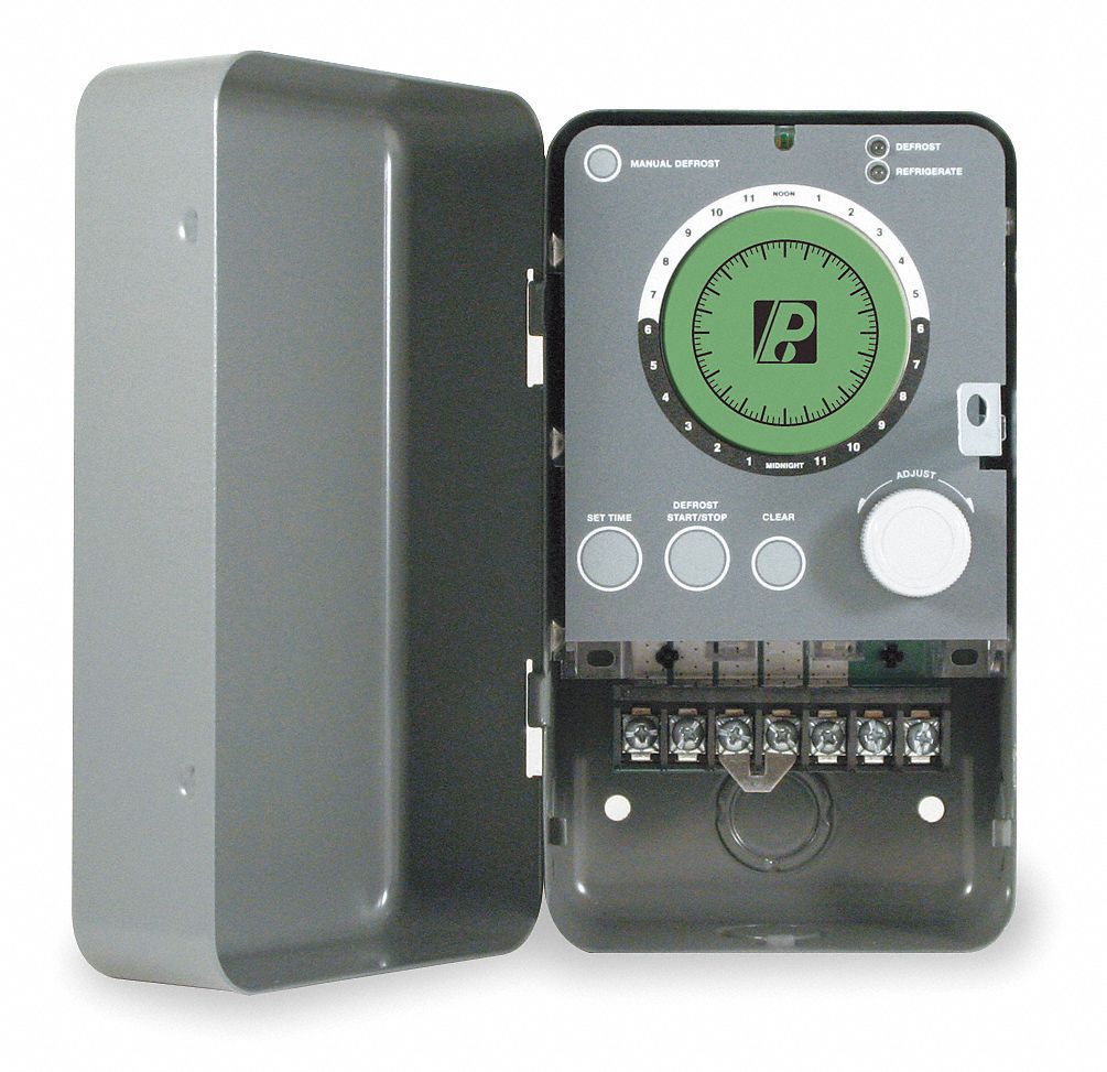
The Paragon® 9045-00 and 9145-00 Universal Defrost Timers (UDT) are the only multi-voltage defrost timers engineered to industry refrigeration standards. Designed to withstand the most rigorous refrigeration applications, this control offers a real-time clock and 100 hours of power loss protection for both time and defrost schedules.
Untitled
Basic information about the Paragon Mechanical and Electronic Defrost Timers
TMDE309ZC TIMER DEFROST 4HR 9MINS
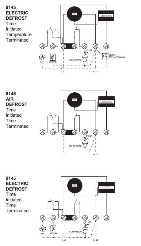
Oct 23, 2018 · 20 Applications and Wiring Diagrams. MECHANICAL. DEFROST. TIMER.. The Paragon® defrost and the Tork® electric timers offer versatility and unbeatable quality to Electric Heat,. Hot Gas or Compressor Shutdown. Closed. Open. Closed . Temperature Terminated - Wiring Diagram. A. B. C. D. E. F. G. Adjustable Defrost Initiation Frequency: One to six times per day.
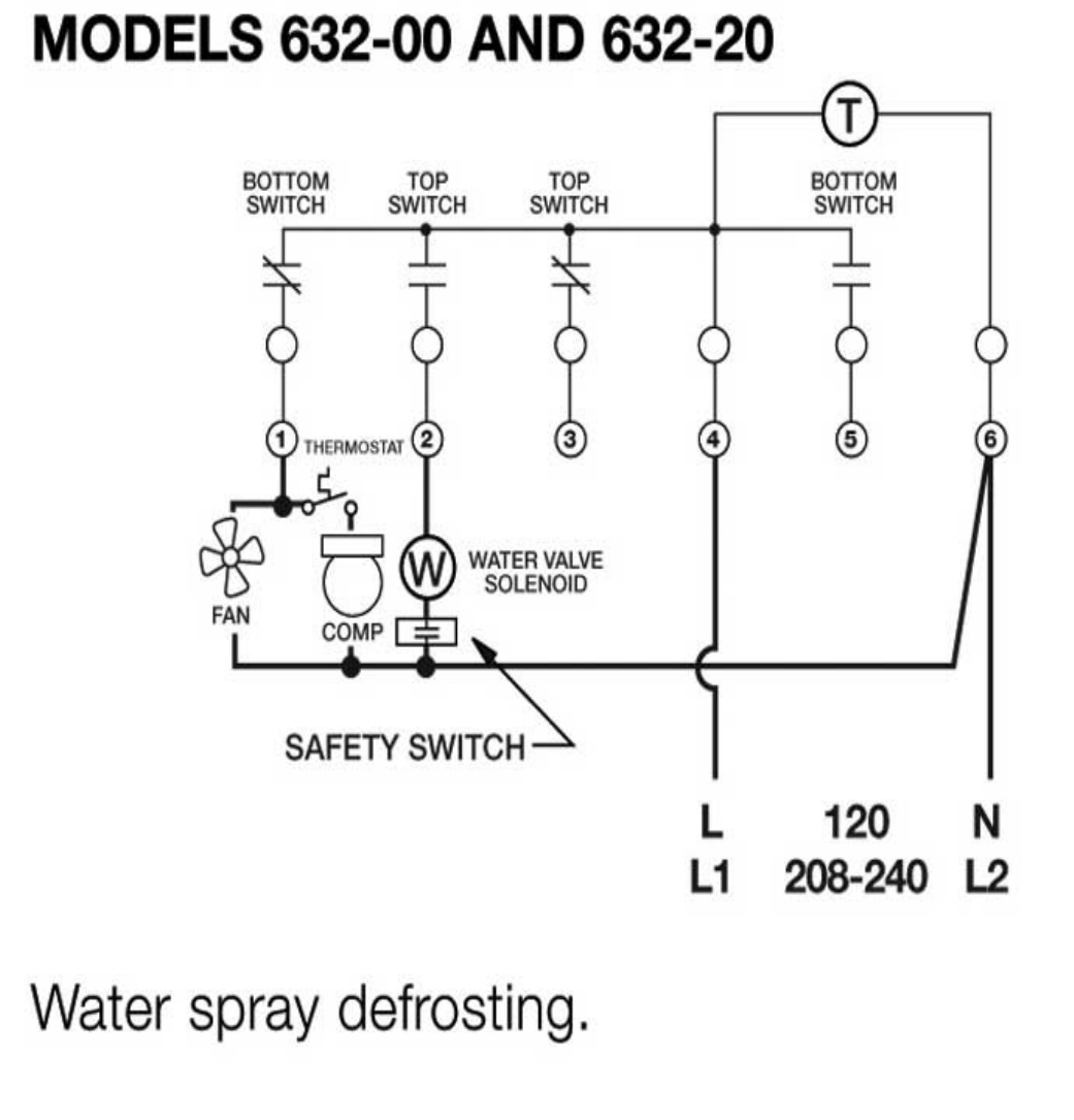
Paragon 632 20 defrost timer
Bear with me, this is probably a stupid question but I can't find any easy diagrams that have proper part numbers or names that I can easily look at and pick that specific part from and order it. Basically I own a 1969 Beetle, and all of the tubing that comes up from the heat channels below the A pillar and comes up to where the fresh air box is is completely dry rotted. I need pretty much all of those ducts except for the Y piece. The problem is I can't find anything specific, so I don't know ...

Paragon Type Tmdb Defrost Timer - China Defrost Timer and ...
Paragon 8045-20 defrost timer wiring diagram Tap image to zoom. Roll over image to zoom. Paragon 8040 series defrost timer Defrost frequency is one to six cycles per day Adjustable back up defrost termination from 4 - 110 minutes (2 minute increments) Time initiated/time terminated Choice of three contact arrangements for electric heat,
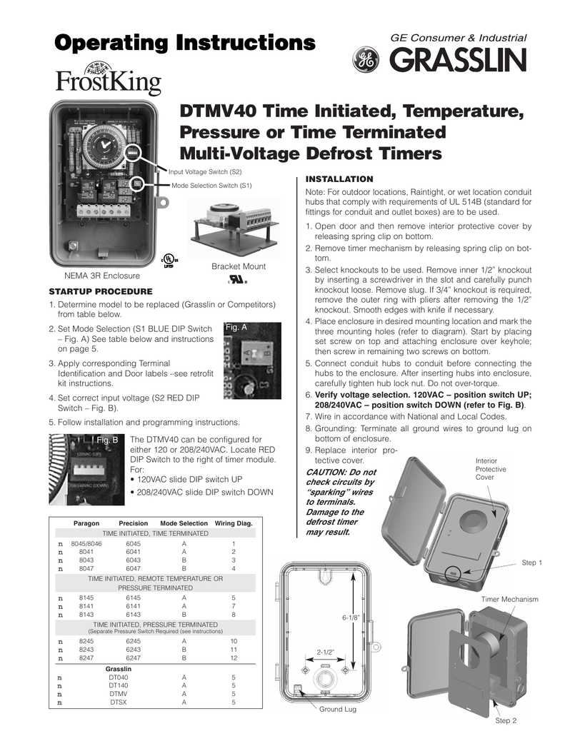
Operating Instructions
Paragon Controls Inc - Airflow Measurement, Control, and Monitoring. THE SENSE ABLE SOLUTION. Engineering & Manufacturing Airflow & Pressure Measurement Systems That Deliver Building Performance. Our airflow and pressure measurement systems and support services bring results through; collaborative design to meet customer requirements, the use ...
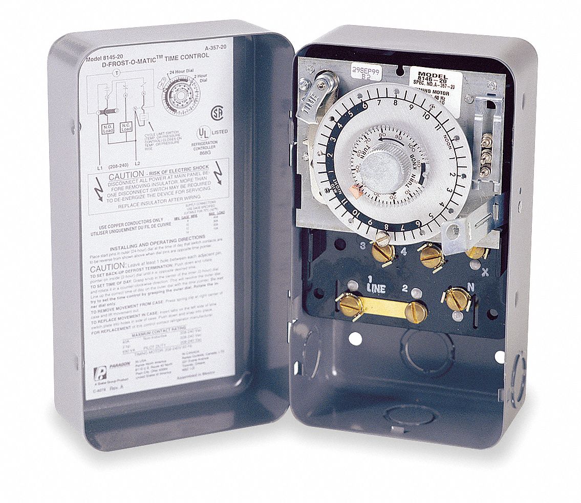
INSTALLATION DATA 8000 SERIES AUTO VOLTAGE DEFROST TIMER
Hello all I'm a total newbie when it comes to this, so I wanted to run this past the community I have traced the basic backbone of my electronics, and have mapped these out in a very simplistic (I'm no engineer) layout. I've omitted fuses, and the connections for the alternator and solar panels. My question is, does the drawing make sense? Is there any fundamental issues here? I don't intend to make many changes to this setup this year, I just want to make sure I understand things properly....

I have an 8141 Paragon defrost timer and have to replace it ...
Collection of paragon defrost timer 8145 20 wiring diagram. A wiring diagram is a simplified traditional photographic depiction of an electrical circuit. It reveals the elements of the circuit as streamlined shapes, and also the power as well as signal links in between the tools.
AUTO VOLTAGE DEFROST TIMERS 8000 SERIES
I have searched far and low and have found bare nothing when it comes to my package car. It is a SV trim level with touch-nav & no Bose premium sound package. I am trying to figure out the correct diagram in order to solder in new speaker wires to the factory wires for a amp install. I want to keep everything as factory as possible OBV. So no fancy EQ HU 🤷♂️

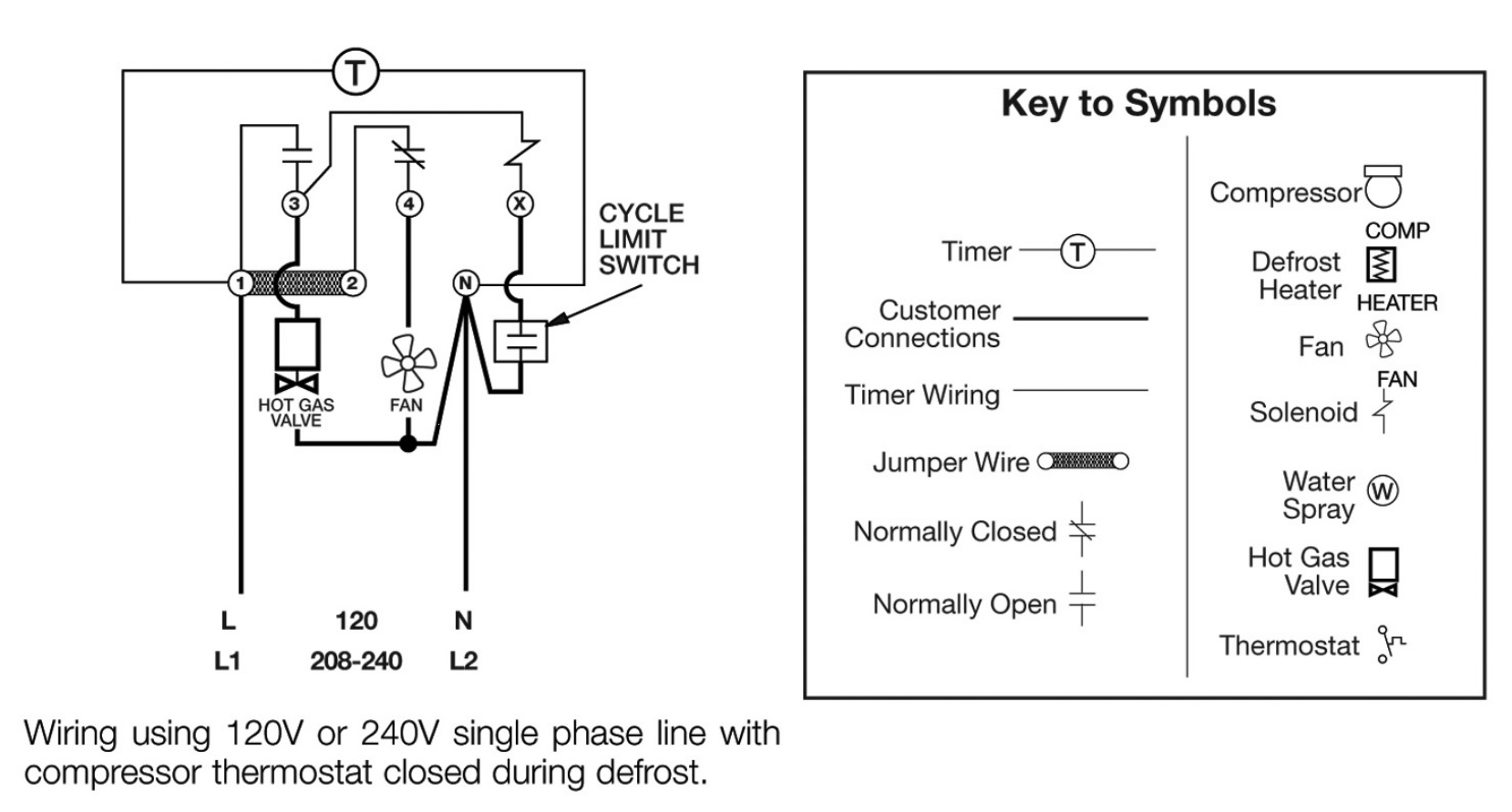
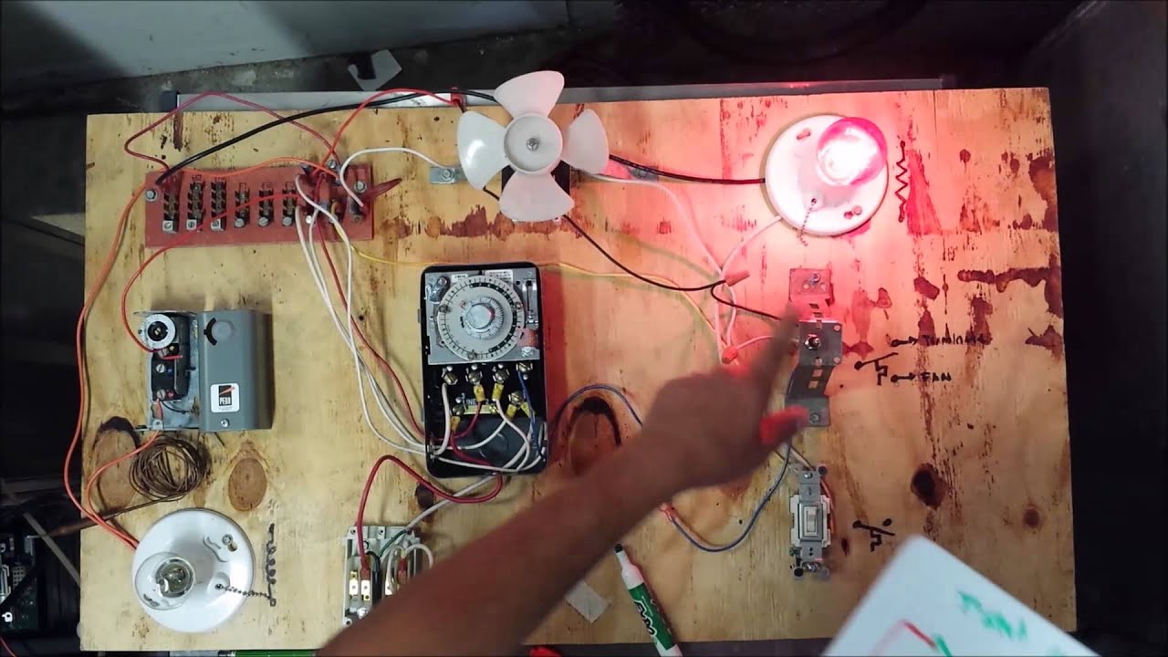
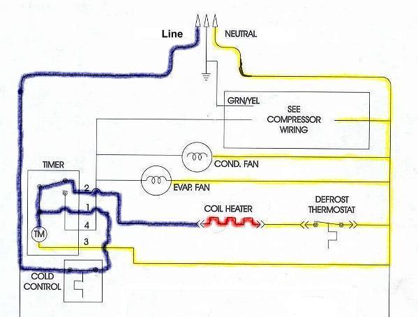
Typical wiring for defrost on a single evaporator freezer
Danby Fridge model: dff8801w Defrost timer part number: 1.01.07.03.001 Hey there. I had a defective defrost timer and pulled it out to replace it. Meanwhile, I forgot which order my wires were connected to the 1,2,3,4 prongs on my defrost timer. I have a double red wire, a blue wire, orange wire, and white wire but don't know which prongs to put them on. Please help!
SERVICE & INSTALLATION MANUAL
Wiring for a single evap freezer system or reach in freezer. Any questions or comments Feel free to ask in the comment section . Thanks for watching 👍. ...
REFRIGERATION
Source: www.beautyboss.co.id I know when we draw up the schematic diagram the. Older frigidaire defrost timer 8000 series auto voltage in frost free refrigerator wiring diagram precision multiple controls official paragon 632 20 fixed frt045gm question servair ltd air time hvac r older frigidaire defrost timer doityourself com community forums installation data 8000 series auto voltage defrost ...

Intermatic Product Catalog Pages 101-150 - Flip PDF Download ...
[http://www.wrxinfo.com/service\_manuals/](http://www.wrxinfo.com/service_manuals/) Been researching some torque specs for suspension stuff and was surprised about the amount of misinformation and confusion out there across forums and videos. Here ya'll go, hope this helps some of you DIYers.

paragon 8145 20 wiring diagram Questions & Answers (with ...
Instruction Manuals. To find a publication quickly, you can use the " Filter " above the list to display by Category. You can also use the Search feature for a specific document title or category. You can sort the " Document Title " or the " Category " column using the button to the right of the column title.
Defrost Time Controls / HVAC/R Defrost Time Controls / HV AC/R
Dimension: 645 x 471. DOWNLOAD. Wiring Diagram Images Detail: Name: paragon 8141 00 wiring diagram – Paragon Timer Wiring Diagram Diagrams Schematics Throughout Defrost Time Clock 0. File Type: JPG. Source: natebird.me. Size: 193.58 KB. Dimension: 1659 x 891.

Refrigerator Defrost Timer at Rs 350/piece | Defrost timers ...
2. Set Defrost Insert pin(s) to desired defrost time(s) on outer dial. 3. Set Defrost Duration Move copper pointer to desired duration of defrost time on inner dial. Install our Commercial Defrost Controls today to understand why Paragon® is Simply the Right Choice™ in Defrost Timers. An ISO 9001 – 2008 Certified Company 1 Year Limited ...
Tesco Heating Elements » Robertshaw Controls (Robertshaw ...
schematron.org
PARAGON COMMERCIAL DEFROST TIMER DIGITAL
If not, probably the wiring is backwards. They generally are good timers. If it has, you may have. how to wire model defrost timer - Paragon Defrost Timer Changing the defrost timer will not require use of a wiring diagram. Results 1 - 37 of 37 The Paragon® Series Auto Voltage Defrost Timer is designed for commercial freezers and refrigerators ...

Defrost Timer - Electrical & In-Line Components - Parts ...
Samsung Refrigerator Defrost Timer Wiring Diagram. mervin.ryan January 29, 2022 Templates No Comments. ... Paragon Defrost Timer Wiring Diagram. 3 Wire Defrost Termination Switch Wiring Diagram. Lg Inverter Refrigerator Wiring Diagram. Ge Monogram Refrigerator Wiring Diagram. Whirlpool Refrigerator Wiring Diagram Pdf. 8 Pin Timer Relay Wiring ...

HOW FREEZER DEFROST TIMER OPERATES - PART 2
28.11.2021 · © Valve Corporation. All rights reserved. All trademarks are property of their respective owners in the US and other countries. #footer_privacy_policy | #footer ...
INSTALLATION DATA 8000 SERIES AUTO VOLTAGE DEFROST TIMER
Click to get the latest Where Are They Now? content.
REFRIGERATION
Answer to Lab 9: Sets in the Java Collection Framework For this week's lab, you will use two of the classes in the Java Collection Framework: HashSet and
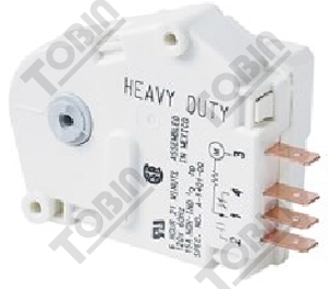
Defrost Timer Control, 120/208/240V AC Voltage, 30 A Amps, 1 SPDT, 1 SPST
Subaru's EJ208 engine was a 2.0-litre horizontally-opposed petrol engine with sequential turbochargers. In Australia, the EJ208 engine was introduced in the 2001 Subaru BE Liberty B4 which, with a manual transmission, produced peak outputs of 190 kW and 320 Nm. From 2002, the BE Liberty B4 was offered with an automatic transmission for which the EJ208 engine was …

Defrost Timer DBZC-825-1GS TMDC825 @ Timer Peti Ais 825 ...
SUPCO Paragon Precision S814100 8141-00 6141-00 ... Normally closed thermostat used with defrost heater. Wiring using 120V or 240V single phase line compressor voltage common to timer. CYCLE LIMIT SWITCH HEATER COMP THERMOSTAT Wiring Diagrams Electric Heat Defrosting S8141 & S8145 Series Wiring Diagrams Electric Heat Defrosting S8041 & S8045 ...
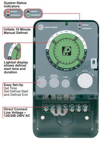
PARAGON COMMERCIAL DEFROST TIMER DIGITAL
Joined: 11/5/2011 (UTC) Posts: 2. The part replacement for the defrost timer has a black wire that was not on the original part. I have confiremd that this is a replacement but the are options for the black wire depending up the original wiring diagram of the unit. I chose version2/procedure 3 as it seemed to fit.
Freezer Defrost Timer Live Operation
Does anyone have a wiring diagram for the fuel pump on a 2017 6.7? After a lot of googlefication all I can find is for 7.3, 6.0, and 6.2. I’m installing a kill switch run to an upfitter switch in the cab for theft prevention.
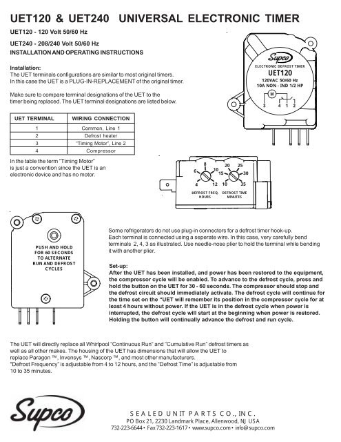
Installation & Operating Instructions - Supco
Your business website represents your brand. Therefore, its functional efficiency is important for your market reputation. Our web development services helps you to develop websites that comply with current industry standards, providing a seamless experience to your end-users.. Our web developers create high-performing websites using state-of-art website development practices.
Paragon SPG-1111-21 Freeze Defrost Timer Fridge Refrigerator | R8001
TIMER. Assortment of Paragon Timer Wiring Diagram it is possible to download totally free. Paragon 8145 20 Wiring Diagram. Please download these Paragon Timer Wiring Diagram by using the download button. DEFROST TIMERS An ISO – Certified Company Features and Benefits The Paragon® and Universal Defrost Timers are the only multi-voltage defrost timers engineered to refrigeration standards. At four defrosts per day, the Paragon Universal Defrost Timer switches last 16 years longer than ...
MECHANICAL DEFROST TIMER 8000 Series
Description: Paragon Defrost Timer Wiring Diagram Paragon Defrost Timer Wiring regarding 20 Wiring Diagram, image size X px, and to view image details please click the image. 8145 20 Timer Wiring Diagram Manual override reverses the current output state. Loads that are ON turn immediately OFF; loads that are OFF turn immediately ON.
Refrigerator Defrost Cycle | Appliance Aid
Looking for Timer, Defrost, 120V, 1 NO, 2NC Switches? Find it at Grainger.com®. With over 1.6M products and 24/7 customer service we have supplies and solutions for every industry.
MECHANICAL DEFROST TIMER 8000 Series
Wiring Diagram. Models , and E -. the wiring diagram chosen. (Default setting B). 14 AWG OR LARGER WIRES RATED AT LEAST ⁰C. LISTED . and Electric Heat. •. •. •. Series Specifications. Uni-Line Applications and Wiring Diagrams. MECHANICAL.Paragon - V Defrost Timer - Designed for commercial freezers and refrigerators, Paragon commercial ...
Untitled
Dec 09, 2018 · Then timer outputs can control 3-phase power using 3-phase contactors Contactor below is 3 phase with V coil http: Link below is for Paragon commercial box-type defrost timers http: I cant seem to find a wiring diagram on how to wire this correctly Link below has wiring diagrams and wiring manuals for V http: According to information from ...
Defrost Time Controls / HVAC/R Defrost Time Controls / HV AC/R
Jun 22, 2021 · Paragon 8145 20 defrost timer wiring diagram. It reveals the elements of the circuit as simplified forms and also the power and also signal connections between the tools. Collection of paragon defrost timer 8145 20 wiring diagram. 8047 20 208 240 for electric heat defrosting auxiliary contact models 50 hz available open open closed 4 110 min.

Defrost Timer Assembly
REFRIGERATION

Paragon timers and manuals:
Part Number: E104282_P
Defrost Timer Control, 120V AC Voltage, 40 A Amps, 1 NO/2 NC


Comments
Post a Comment