38 ps2 controller diagram
PlayStation 2 Controller Plug Diagram. Joseph Howell February 19, 2019 13:51. Follow. Q: I am wiring up an arcade stick for a PlayStation 2. What is the proper pinout for the console end of the PS2 controller? ... Playstation 2 Controller Connector pinout. 9 pin Sony Playstation proprietary connector. Ask a question. Comment. Edit. Submit New. This pinout is associated with 1 compatible devices or models. Show them>.
Ps2 Controller Wiring Diagram – wiring diagram is a simplified normal pictorial representation of an electrical circuit. It shows the components of the circuit as simplified shapes, and the talent and signal links in the midst of the devices. A wiring diagram usually gives guidance very nearly the relative perspective and accord of devices ...

Ps2 controller diagram
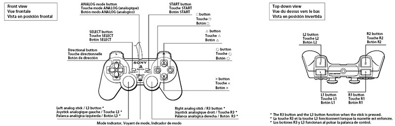
Commands in pad controllers are made by having a small, conductive plate at the bottom of each button press down directly onto the PCB to complete the circuit between the ground and signal paths. Often conductive rubbery nodes (usually black) are placed where buttons are pressed. Using A Playstation 2 Controller with your Arduino Project It occurred to me one day as I was designing a little box with some joysticks and a few buttons to control a ... diagram below shows each of the names for the buttons and sticks. The buttons with the coloured shapes can also be referred to by the names PSB_TRIANGLE, PSB_CIRCLE, The Definitive PS2 Trimming GuidePreface . This guide focuses only on the 7900X series motherboard as it is the smallest PS2 motherboard with its integration of the custom ASIC. The guide will feature two trims at different skill levels that both remove essential components for the operation of the disc drive.
Ps2 controller diagram. Dual force 2, programmable controller for PSX, PSONE, and PS2. The control board pins are numbered, but if unable to see due to the resin, pin one has a square PCB pad. If looking at the control from underside, with the lower casing removed, the pins can be counted sequentially from left to right. There should be 9 in total. Esse video vou mostrar o diagrama do Controle PS2.No video 1 mostro o diagrame também, mais existe muitos fabricantes que por sua vez muda o diagrama na plac... I don't even think PS2 controllers are USB (I could be wrong though). an old PC controller; opened it; snipped the USB wires and used the.Logitech Ps 2 Controller Wire Diagram Schematics (+90 More Diagrams) There are different panelization and de-panelization methods depending on the application of the PCB, thickness, shape, component layout ... Mar 12, 2019 · Find your ps2 controller wiring diagram usb here for ps2 controller wiring diagram usb and you can print out. Search for ps2 controller wiring diagram usb here and subscribe to this site ps2 controller wiring diagram usb read more!
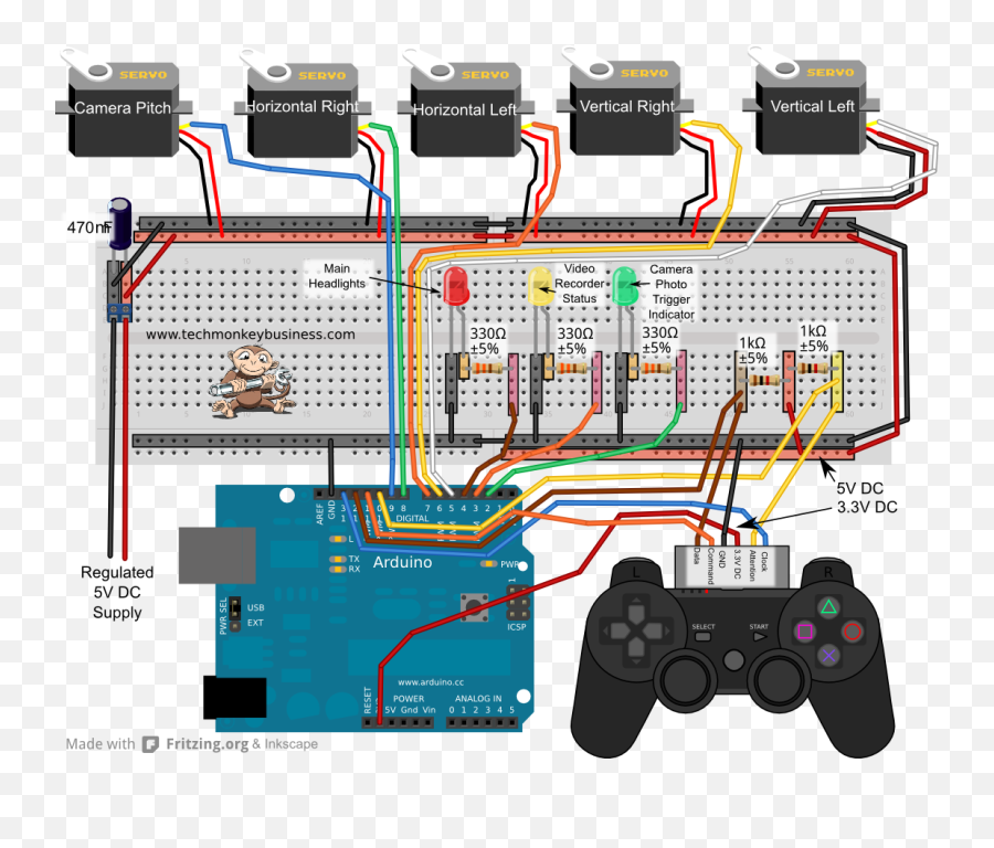
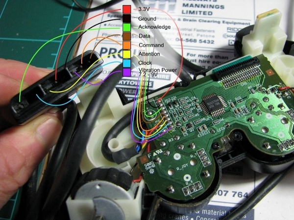
Step 1 DualShock 2 Disassembly. First, check that the connection port of your controller (whether wireless or not) has all the pins. If you have a wired controller (a controller with a cable that connects directly to your console) try bending it in different directions. This may recconect broken connections within the controller cabel and could ... Dec 20, 2019 - Circuit Diagram of the PS2 Controller Demonstration Rig. Wire Colors and Functionality: There are 9 wires, 6 wires are needed at a minimum to talk to the controller: (clock, data, command, power & ground, attention).To operate vibration motors, motor_power is also needed. Brown – Data: Controller -> PlayStation.This is an open collector output and requires a pull-up resistor (1 to 10k, maybe more). ). (A pull-up resistor is needed because the ... The official SONY Controllers will operate on 3.3V, and not on 5V, however the unofficial controllers mostly will work on 5V. All controlers WILL work on 3.3V. The main board in the PSX also has a surface mount 750mA fuse that will blow if you try to draw to much current through the plug (750mA is for both left, right and memory cards).
The standard PS2 controller has 15 buttons; all of them, except for Analog, Start and Select are analog. They include: four buttons arranged as a directional pad on the top left Analog, Start and Select buttons in the top middle four action buttons on the top right two action buttons on the front left two action buttons on the front right The basic timing diagram of transmitting a packet from a PS2 device to a host is shown in Figure 8.1, in which the data and clock signals are labeled ps2d and ps2c, respectively. The data is transmitted in a serial stream, and its format is similar to that of a UART. Connection Diagram Here we have interfaced the PS2 Wireless Controller with an Arduino. Upon each button press the Arduino receives the RF signal on the PS2 receiver and displays the it on the alphanumeric LCD module. We followed the standard PS2 protocol for realizing the communication algorithm, identical to the SPI protocol. Jan 17, 2022 · Here are a number of highest rated Ps2 Controller Wiring Diagram pictures on internet. We identified it from obedient source. Its submitted by supervision in the best field. We agree to this kind of Ps2 Controller Wiring Diagram graphic could possibly be the most trending subject bearing in mind we portion it in google improvement or facebook.
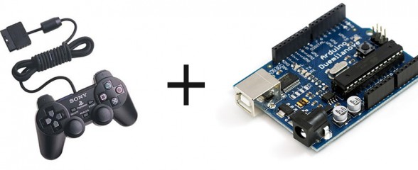
Arduino Robot With PS2 Controller (PlayStation 2 Joystick ...
Sony PS2 service manual download. Power requirements: 220-240 V AC, 50/60 Hz. Power consumption: 50 W. Dimensions: 301 ´ 78 ´ 182 mm (w/h/d) Mass: 2.4 kg. Inputs/ Outputs on the front.

PW11X2-2 PS2 Controller Schematics Circuit Diagram Saitek ...
the simple goal in wiring is to have the grounds and signals of each device linked to the ground and desired corresponding signals on the pcb. as well as ps1 controller wiring diagram moreover wiring diagram for ps3 moreover ps2 controller cord wiring diagram moreover keyboard wiring diagram also cable harness board along with how to wire an …
Ps2 Controller Arduino And Servo - Arduino Game Controller ...
Atari 5200 Playstation 2 Dual Shock Controller Adapter Dr Scott M Baker. Ps2 playstation 2 controller usb cable to a ps3 game adaptor diy converter using with interfacing wireless arduino wiring diagram interface circuit for 12 windows forum reprogrammable adapt old controllers the ps keyboard tom s hardware joystick pcb and on arduinos 3 rewire atari 5200 dual shock psx pc parallel port ...

PS2 Motor Controller | A small project I did, using a Playst ...
Select 0 Left Joystick Click 1 Right Joystick Click 2 Start 3 DPad U 4 DPad R 5 D Pad D 6 DPadL 7 L2 8 R2 9 L1 10 R1 11 Triangle 12 Circle 13 X 14 Square 15 Axes. Button lets you exit a menu or cancel an action. Select the audio output format for playback of DVDs or BDs.
My "PS3/Generic Gamepad" (Actually a PS2 controller with USB ...
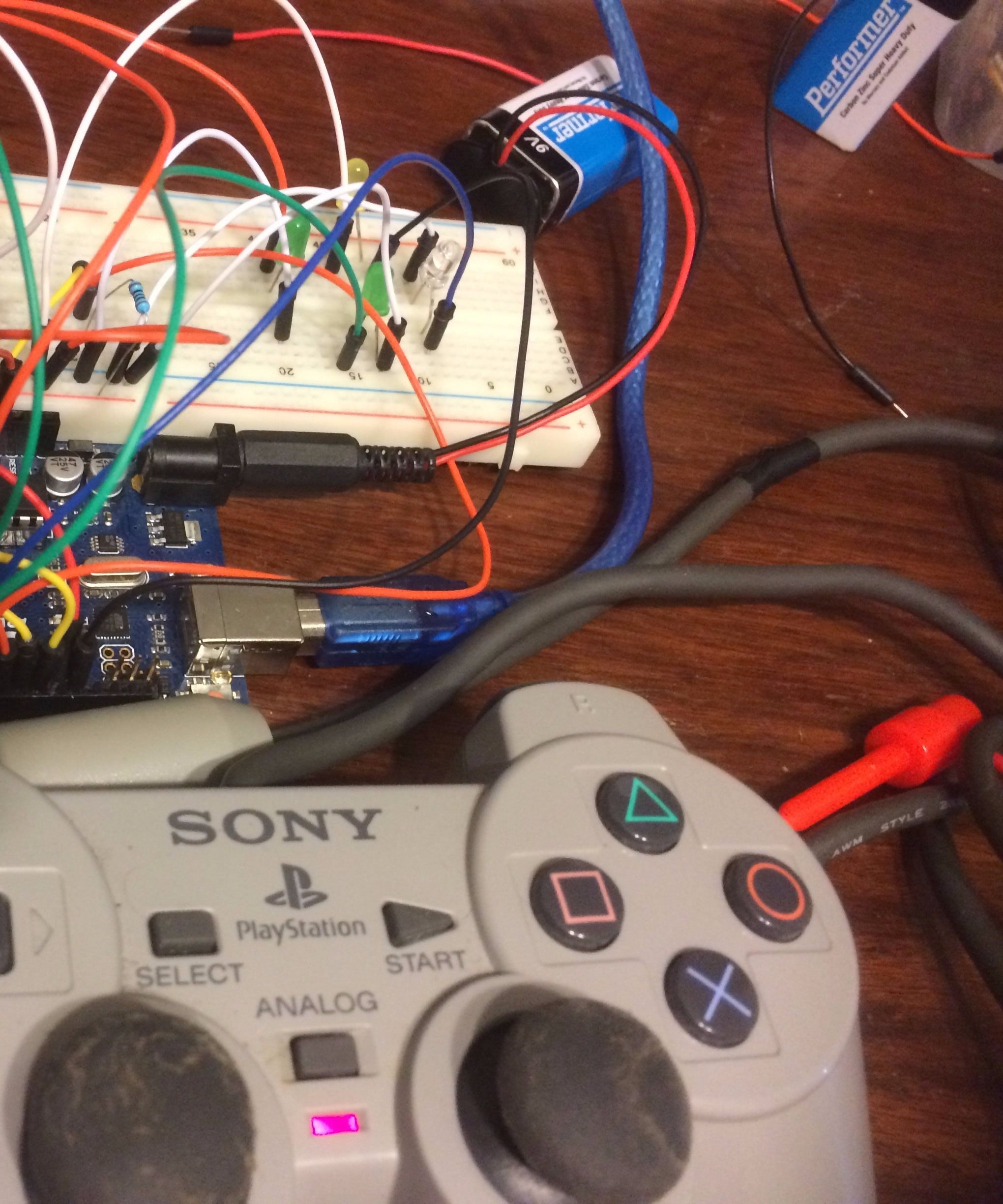
View "SCHEMATICS" to see visual diagrams on how everything is wired up. There are diagrams for the motor board, sensor shield, PS2 controller and also an additional motor connected to a bread board for a flipper/spinner. The flipper/spinner is programmed to activate when the X button is pressed on the PS2 controller.
PS2 Wire Controller and Arduino (control LEDs) : 3 Steps ...
Ps2 playstation 2 controller usb cable to a cáp chuyễn tay cầm ps1 sang arduino game wiring diagram wireless how connect diy converter project 058a windows forum ps keyboard tom s hardware connector at the reprogrammable Interfacing A Ps2 Playstation 2 Controller Curious Inventor If I Attach A Usb Cable To Ps2 Controller Will […]

Building A PS3 Controller Using Random/PS2 Parts!
The basic timing diagram of transmitting a packet from a PS2 device to a host is shown in Figure 8.1, in which the data and clock signals are labeled ps2d and ps2c, respectively. The data is transmitted in a serial stream, and its format is similar to that of a UART.
shows the connection diagram of master controller. In adding ...
Hi, i was wondering if anyone knew of a ps2 controller to usb wiring diagram. I know you can buy an adapter but i am looking for a picture or article that show you were to connect the 8ps2 wires to the 4usb wires. Any information would help and thx in advance. Excon Member 5.1k 83 Posted December 18, 2013
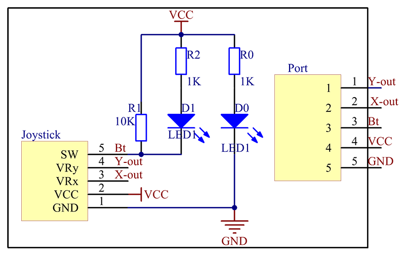
Joystick PS2 Module - Wiki
Follow the schematic diagram to connect the PS2 controller port, Bluetooth module, and USB power port to the Arduino. Plug in a PS2 controller and pair with a Bluetooth enabled device to give it a test. Use a Bluetooth controller testing app (like the Game Controller Test app for Android) to check that all buttons and both analog sticks ...
PS2 Controller Diagram | Holland Hume | Flickr
Sep 18, 2018 · Hi, i was wondering if anyone knew of a ps2 controller to usb wiring diagram. I know you can buy an adapter but i am looking for a picture or.Ps2 controller wiring diagram When i open my ps2 the controller starts vibrating and won't stop the controller has a cut in the wire to connect to the game Posted by Anonymous on May 05, Interfacing a PS2 ...
PlayStation 2 Controller Arduino Library v1.0 « The Mind of ...
LES COMPOSANTS IDENTIFIÉS PAR UNE MARQUE SUR LES DIAGRAMMES SCHÉMATIQUES ET LA LISTE DES PIÈCES SONT CRITIQUES POUR LA SÉCURITÉ DE FONCTIONNEMENT. NE REMPLACER CES COM- POSANTS QUE PAR DES PIÈCES SONY DONT LES NUMÉROS SONT DONNÉS DANS CE MANUEL OU DANS LES SUPPLÉMENTS UBLIÉS PAR SONY. CAUTION Replace the battery with a Sony CR2032 battery.

Free Shipping PS2 Wireless Controller Transceiver Control Board RC 51 Single Chip Microcomputer Arduino Robot Smart Car
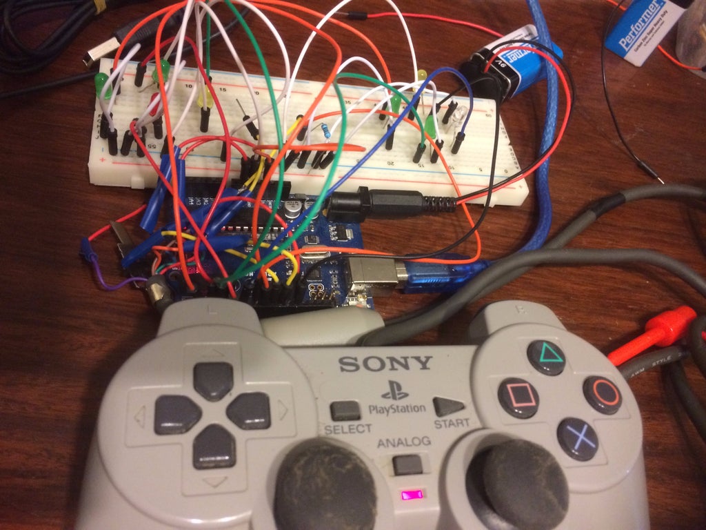
Step 1: Step 1 : Wiring PS2 Controller and Arduino. This is the part that took me quite a while, try to keep the plastic case connector and follow the wiring digram, in my case I cut the wire and lost track of the ordering or the wire label. But I figured it out in the end.
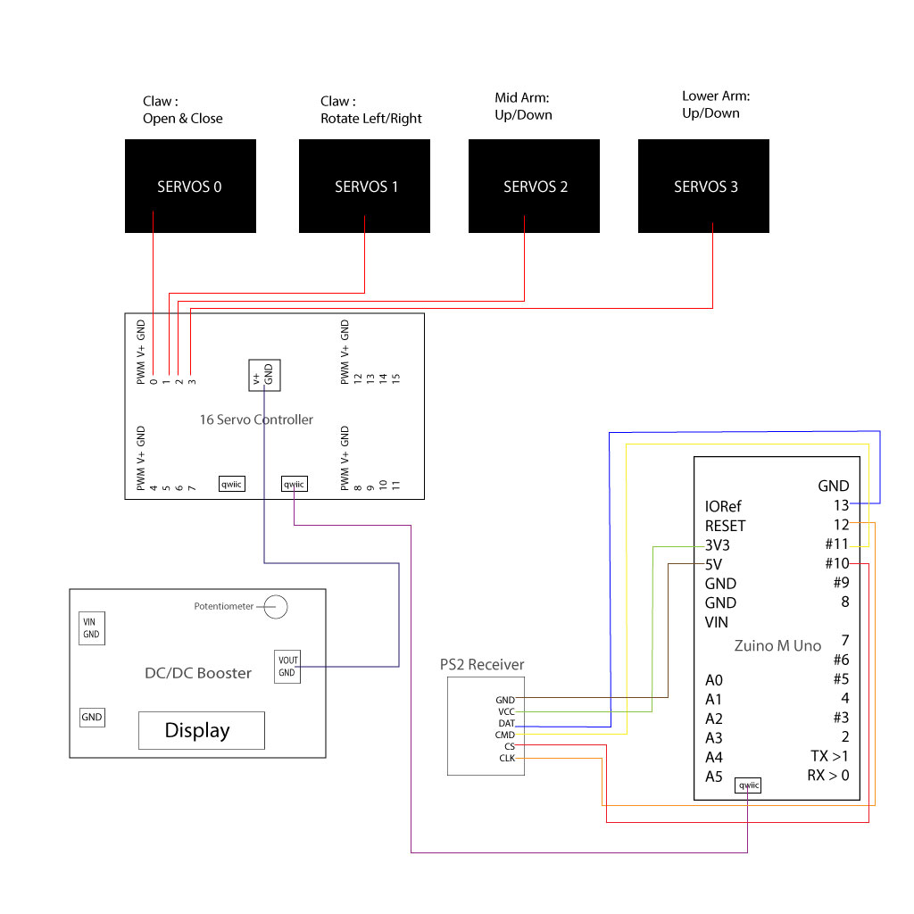
Control a Robotic Arm with Zio - Part 2
PS2 - PS2 Controller Version (v1.0) Feb 12, 2009 4 CPU to PS/2 Device - Communications Overview The PS2 Controller provides the interface between a processor (host) on the one side and a PS/2 device (keyboard or mouse) on the other. The host processor sends data to and receives data from the PS2 Controller, on the DATAI and DATAO buses ...

PS2 Controller Drivers For Windows...FINALLY... - YouTube
The Definitive PS2 Trimming GuidePreface . This guide focuses only on the 7900X series motherboard as it is the smallest PS2 motherboard with its integration of the custom ASIC. The guide will feature two trims at different skill levels that both remove essential components for the operation of the disc drive.
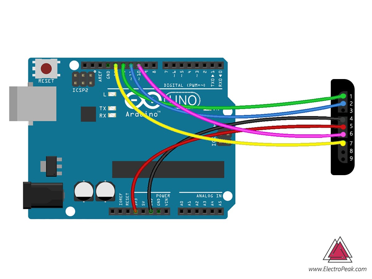
How to Interface PS2 Wireless Controller w/ Arduino - Arduino ...
Using A Playstation 2 Controller with your Arduino Project It occurred to me one day as I was designing a little box with some joysticks and a few buttons to control a ... diagram below shows each of the names for the buttons and sticks. The buttons with the coloured shapes can also be referred to by the names PSB_TRIANGLE, PSB_CIRCLE,
PS2 Wire Controller and Arduino (control LEDs) : 3 Steps ...
Commands in pad controllers are made by having a small, conductive plate at the bottom of each button press down directly onto the PCB to complete the circuit between the ground and signal paths. Often conductive rubbery nodes (usually black) are placed where buttons are pressed.
S619S620C WIRELESS CONTROLLER FOR PS2 Schematics 404465 ...

DualShock 2 Controller Dimensions & Drawings | Dimensions.com

Digitalduino: Interfacing a PlayStation 2 (PS2) Controller ...

Reverse Engineering PS2 Controller by Michael Ly at Coroflot.com

PS2 controller working! | Mecharobotics's Blog

Ico's control scheme | Download Scientific Diagram

PRX7-1 PS2 Controller Schematics Circuit Diagram Saitek ...
Interfacing a PS2 (PlayStation 2) Controller - Curious Inventor

Tech Tear Down – Comparing Two Video Game Controllers ...

Interfacing PS2 Wireless Controller With Arduino

First attempt making an exploded view of a PS2 controller ...

PS2 Controller to USB Controller Without Adapter.. - YouTube

How to Make PS2 Controller With Arduino and NRF24L01 ...

DOIT UNO Starter Kit for Arduino Project with PS2 Controller, UNO Board, Motor Drive Shield Board, Tracking Module for DIY

Low-cost PS2 controller matches Sony's version sans the cord

Is my current plan for wiring two game controller boards in ...

Super Star Video Games - PS2 Dualshock 2 Wired Controller for ...
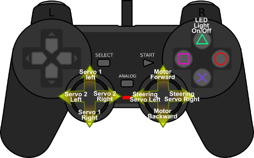
Using A Playstation 2 Controller with your Arduino Project ...
ps2 controller - Prices and Promotions - Feb 2022 | Shopee ...
PS2 Controllers on Arduinos | TechMonkeyBusiness

PS2 Wireless Remote Control Robot Controller Using PIC Micro ...

Interfacing PS2 Wireless Controller With Arduino


Comments
Post a Comment